Download

1 / 24
1.03k likes | 4.1k Vues
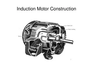
Induction Motor Drive. Why induction motor (IM)? Robust; No brushes. No contacts on rotor shaft High Power/Weight, Lower Cost/Power ratios Easy to manufacture Almost maintenance-free, except for bearing and other “external” mechanical parts Disadvantages Essentially a “fixed-speed” machine

E N D
Induction Motor Drive • Why induction motor (IM)? • Robust; No brushes. No contacts on rotor shaft • High Power/Weight, Lower Cost/Power ratios • Easy to manufacture • Almost maintenance-free, except for bearing and other “external” mechanical parts • Disadvantages • Essentially a “fixed-speed” machine • Speed is determined by the supply frequency • To vary its speed need a variable frequency supply • Motivation for variable-speed AC drives • Inverter configuration improved • Fast switching, high power switches • Sophisticated control strategy • Microprocessor/DSP implementation • Applications • Conveyer line (belt) drives, Roller table, Paper mills, Traction, Electric vehicles, Elevators, pulleys, Air-conditioning and any industrial process that requires variable-speed operation. • The state-of-the-art in IM drives is such that most of the DC drives will be replaced with IM in very near future. Dr. Zainal salam; Power Electronics and Drives (Version 2),2002, UTMJB
Torque production (1) • Only “squirrel-cage” IM (SCIM) is considered in this module • Neglecting all harmonics, the stator establishes a spatially distributed magnetic flux density in the air-gap that rotate at a synchronous speed, w1: where we: supply frequency (in Hz) p: pole pairs (p=1for 2 pole motor, p=2 for 4 pole motor etc) • If the rotor is initially stationary, its conductor is subjected to a sweeping magnetic field, inducing rotor current at synchronous speed. • If the rotor is rotating at synchronous speed (i.e. equals to f1), then the rotor experience no induction. No current is induced in the rotor. Dr. Zainal salam; Power Electronics and Drives (Version 2),2002, UTMJB
Torque production (2) • At any other rotor speed, say wm, the speed differential wi-w2 creates slip. Per-unit slip is defined as: • Slip frequency is defined as: w2=w1-wm. • When rotor is rotating at wm., rotor current at slip frequency will be induced. • The interaction between rotor current and air-gap flux produces torque. Dr. Zainal salam; Power Electronics and Drives (Version 2),2002, UTMJB
Single-phase Equivalent Circuit (SPEC) Dr. Zainal salam; Power Electronics and Drives (Version 2),2002, UTMJB
SPEC, referred to stator • From previous diagram, SPEC is a dual frequency circuit. On the stator is w1 and on the rotor wm • Difficult to do calculations. • We can make the circuit a single frequency type, by referring the quantities to the stator Dr. Zainal salam; Power Electronics and Drives (Version 2),2002, UTMJB
Rotor current Dr. Zainal salam; Power Electronics and Drives (Version 2),2002, UTMJB
Performance calculation using SPEC Dr. Zainal salam; Power Electronics and Drives (Version 2),2002, UTMJB
Performance calculation (2) Dr. Zainal salam; Power Electronics and Drives (Version 2),2002, UTMJB
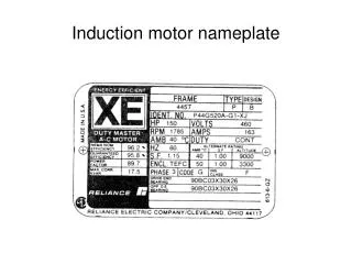
Example calculation • A single phase equivalent circuit of a 6-pole SCIM that operates from a 220V line voltage at 60Hz is given below. Calculate the stator current, output power, torque and efficiency at a slip of 2.5%. The fixed winding and friction losses is 350W. Neglect the core loss. Dr. Zainal salam; Power Electronics and Drives (Version 2),2002, UTMJB
Calculation (solution) Dr. Zainal salam; Power Electronics and Drives (Version 2),2002, UTMJB
Starting current • For the previous example, Calculate the stating current when motor is first switched on to rated applied voltage. Dr. Zainal salam; Power Electronics and Drives (Version 2),2002, UTMJB
Approximate SPEC Dr. Zainal salam; Power Electronics and Drives (Version 2),2002, UTMJB
Single (fixed supply) frequency characteristics Dr. Zainal salam; Power Electronics and Drives (Version 2),2002, UTMJB
Single frequency characteristics Dr. Zainal salam; Power Electronics and Drives (Version 2),2002, UTMJB
Single frequency characteristic • As slip is increased from zero (synchronous), the torque rapidly reaches the maximum. Then it decreases to standstill when the slip is unity. • At synchronous speed, torque is almost zero. • At standstill, torque is not too high, but the current is very high. Thus the VA requirement of the IM is several times than the full load. Not economic to operate at this condition. • Only at “low slip”, the motor current is low and efficiency and power factor are high. Dr. Zainal salam; Power Electronics and Drives (Version 2),2002, UTMJB
n IM Typical IM Drive System BLOCK DIAGRAM Supply Rectifier and Filter 3-phase Inverter CIRCUIT Dr. Zainal salam; Power Electronics and Drives (Version 2),2002, UTMJB
Variable speed characteristics • For variable speed operation, the supply is an inverter. • The frequency of the fundamental AC voltage will determine the speed of IM. To vary the speed of IM, the inverter fundamental frequency need to be changed. • The inverter output frequency must be kept close to the required motor speed. This is necessary as the IM operates under low slip conditions. • To maintain constant torque, the slip frequency has to be maintained over the range of supply frequencies. Dr. Zainal salam; Power Electronics and Drives (Version 2),2002, UTMJB
Variable voltage, variable frequency (VVVF) operation • In order for maximum torque production, motor flux should be maintained at its rated value. Dr. Zainal salam; Power Electronics and Drives (Version 2),2002, UTMJB
Constant Torque region • Hence for VVVF operation, there is a need to control the fundamental voltage of the inverter if its frequency (and therefore the frequency of the IM) need to be varied. • To vary the fundamental component of the inverter, the MODULATION INDEX can be changed. • The rated supply frequency is normally used as the base speed • At frequencies below the base speed, the supply magnitude need to be reduced so as to maintain a constant Volt/Hertz. • The motor is operated at rated slip at all supply frequencies. Hence a “constant torque” region is obtained. Dr. Zainal salam; Power Electronics and Drives (Version 2),2002, UTMJB
Constant Torque Region Dr. Zainal salam; Power Electronics and Drives (Version 2),2002, UTMJB
Constant Power region • Above base speed, the stator voltage reaches the rated value and the motor enters a constant power region. • In this region, the air-gap flux decreases. This is due to increase in frequency frequency while maintaining fixed voltage. • However, the stator current is maintained constant by increasing the slip. This is equivalent to field weakening mode of a separately excited DC motor. Dr. Zainal salam; Power Electronics and Drives (Version 2),2002, UTMJB
Constant Power region Dr. Zainal salam; Power Electronics and Drives (Version 2),2002, UTMJB
VVVF Summary Dr. Zainal salam; Power Electronics and Drives (Version 2),2002, UTMJB
Examples • A three-phase 4-pole, 10 horsepower, 460V rms/60Hz (line-to line) runs at full-load speed of 1746 rpm. The motor is fed from an inverter. The flux is made to be constsnt. Plot the torque-speed graphs for the following frequency: 60Hz, 45 Hz, 30Hz, 15Hz. • A three-phase induction motor is using a three-phase VSI for VVVF operation. The IM has the following rated parameters: • voltage: 415V (RMS) • frequency: 50Hz • slip (p.u) 5% • pole pair 2 • If the inverter gives 415V (RMS) with modulation index of 0.8, calculate the required modulation index if the motor need to be operated at rotor mechanical speed of 10Hz. Dr. Zainal salam; Power Electronics and Drives (Version 2),2002, UTMJB