Key Features and Operation Principles of Induction Motors
Induction motors are essential in industrial applications due to their rugged design and reliability. They display a simple construction, low cost, and minimal maintenance requirements. With efficient operation and no need for additional starting motors, they serve as the workhorses of industry. The two main types of induction motors are squirrel cage and wound rotor. Operating on the principle of electromagnetic induction, these motors utilize 3-phase AC to create a rotating magnetic field which induces voltage in the rotor. Understanding slip and torque relationships is crucial for their effective application.


Key Features and Operation Principles of Induction Motors
E N D
Presentation Transcript
Module PE2 INDUCTION MOTOR
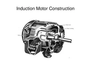
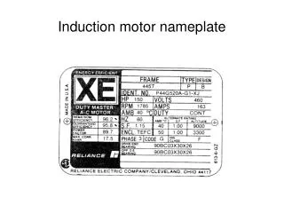
Induction Motor Salient features of an Induction motor are- Simple and rugged construction Low cost and minimum maintenance High reliability and sufficiently high efficiency Needs no extra starting motor; need not be synchronized the workhorse of industry!
Two kinds of AC generators Permanent magnet synchronous machine For type 4 For Types 2, 3 Steam & Gas Turbines Hydro-gens For Type 1
Types of Induction motor Induction motor Squirrel Cage rotorWound rotor Rotor consists of thick copper Rotor has 3-phase bars short-circuited at ends windings w/ slip rings (no external connection) for external connection
___________ sync motor induction motor armature - on stator windings - 3 of them - AC SAME - supplied from line - creates rotating mag. fld. field - on rotor - on rotor windings - 1 winding - 3 windings - DC - AC - current supplied by - current is induced! external source mech - same as speed of rotation - less than speed of speed of of magnetic field. Rotation of mag. fld. Rotor - wm=ws=(2/p)(377) - wm<ws=(2/p)(377)
Synchronous Machine Structure Phase A STATOR (armature winding) ROTOR (perm magnet) + 120° N Phase B One pole pair (p=1) + S The negative terminal for each phase is 180 degrees from the corresponding positive terminal. + For synchronous machines used in wind turbines, the rotor carries a permanent magnet. The two magnetic fields (one from stator and one from rotor) interact to produce torque. Phase C Air Gap
Induction Machine Structure Phase A STATOR (armature winding) ROTOR (Squirrel cage) + 120° Phase B + Voltage is induced within rotor windings by relative motion (SLIP) between those windings and magnetic field produced by stator (Faraday’s Law). Then two magnetic fields (one from stator and one from rotor) interact to produce torque. The (not shown) negative terminal for each phase is 180 degrees from the corresponding (shown) positive terminal + Phase C Air Gap
Operation of an Induction motor Operates on the principle of Induction Apply 3 phase voltage to arm. wdgs. Rot mag fld develops in machine: ws=(2/p)377 Relative motion between rotor wdg and mag fld induces voltage and current in rotor wdgs. Force on rotor because of Lorentz force law: F=ILxB Rotor rotates, but slips relative to mag. fld. “A transformer with a rotating secondary.”
Transformer Per-phase Equivalent Circuit An impedance …An induction machine may be thought of as a transformer with a rotating secondary.
Induction Machine Per-phase Equivalent Circuit I’2 Variable resistance with “s” The main difference between the Xfmr equivalent cct and the induction machine equivalent cct is the loading: the Xfmr load is an actual impedance whereas the induction machine load looks like a variable resistance that depends on “s”.
Induction Machine Per-phase Equivalent Circuit I’2 What does the induction mach load represent? It represents the power provided to or from the shaft. Thus the induction mach load is a purely “real” load since energy transfer by mechanical means must be MW only.
Induction Machine Per-phase Equivalent Circuit Observe that the resistance value is given by: I’2 Req= R2’ is the rotor resistance referred to the stator. But what is “s”?
Induction Machine - Slip s is “slip” which quantifies how much the rotor “slips” behind the stator-produced rotating magnetic field. More precisely, slip is • the amount (in electrical radians/sec) by which • the rotational speed of the stator rotating magnetic field exceeds • the rotational speed of the rotor • normalized by the rotational speed of the stator rotating magnetic field Slip cannot be 0 in steady-state because if it were, there would be no induced Vno I flow in rotor windings. If rotor velocity in mechanical rad/sec is Ωm, and p=number of pole pairs on the rotor, then:
Induction Machine - Speeds We may also write this in terms of mechanical revolutions per minute (rpm), denoted by n, according to: Convert Ω to n: Or, since Ωm=ωm/p, Ωs=ωs/p, convert ω to n: Or, since ω=2πf, convert fs to ns:
Induction Machine - Example Example: Consider a four-pole 60Hz induction machine. Compute slip, Ωm, and ωm for the following values of rpm rotor speed: 0, 500, 1000, 1750, 1800, 1850, 2600, 3600. Solution: To make these computations, we first compute synchronous speed: or Then we can use the following:
Induction Machine – Freq of Rotor Currents Fact 1: The rotor must have speed (ωm) which differs from speed of rotating magnetic field (ωs). Otherwise, no voltage is induced in rotor windings (no relative motion!). Fact 2: Constant torque only exists if the two rotating magnetic fields (one from stator currents and one from rotor currents) are at the same speed. Speed of rotating magnetic field from rotor= rotor speed + {rotating magnetic field speed relative to rotor} Frequency (rad/sec) of rotor currents.
Exact equivalent (per phase) circuit of an Induction motor I’2 Stator winding Air gap Mechanical load Rotor winding Pin PG PD
R1is the stator resistance per phase X1 is the equivalent rotor reactance per phase R2’ is the equivalent rotor resistance per phase referred to the stator X2’ is the equivalent rotor reactance per phase referred to the stator Rc is the resistance representing core losses Xm is the magnetizing reactance per phase V1 is the per phase supply voltage to the stator s is the slip of the motor
IS IT A XFORMER WITH A ROTATING SECONDARY? The voltage transformation from stator to rotor is not apparent from our model. We are actually using a “transformed” rotor circuit model where rotor quantities have been “referred” to the stator side of the voltage transformation. This is the reason for the “primed” notation. Calculations using this model will provide answers corresponding to physical I,V,Z measurements on the stator side but not on the rotor side.
What about power? Any proper power calculation performed with this model will correspond to physical measurements. Often, we are interested in Pin and PD. Power into terminals of motor Power delivered to mechanical load • Note that PD here is the same as PM in the notes.
We may also compute power crossing the airgap and supplying the rotor. This is PG. This would include both the mechanical load and also the losses in the rotor winding. So…. This shows us that we can simplify our circuit model as illustrated in the following two slides, but one must take care to understand what the load resistance means !
Here, the power dissipated by the load resistance equals the power developed at the shaft. This power does not include the power dissipated by the rotor winding resistance. X’2 R’2 R1 X1 R’2 (1-s)/ s Rc Xm
Here, the power dissipated by the load resistance equals the power across the airgap to the rotor. This power includes the power dissipated by the rotor winding resistance. X’2 R1 X1 R’2 / s Rc Xm
Torque expression: But recall that: Substitution yields:
So, assuming we know speed (or slip), then computing torque reguires getting I’2. We will do this using Thevenin’s Theorem. I’2 Za=R1+jX1 X’2 Zb= Rc//jXm V1 R’2 / s Find Thevenin looking in here.
Za=R1+jX1 Zb= Rc//jXm Vth V1
I’2 Zth X’2 Vth R’2 / s So it is very easy to see that:
Procedure for getting torque vs. slip (or speed) relation. • Determine Zb=Rc//jXm • Compute Zth=Za//Zb • Compute Vth=V1 x Zb/(Za+Zb) • Assume a value of s 1. Compute I’2 from 2. Compute Td from Now let’s plot Td vs. slip…….
Slip 1 0 speed 0 ws
Calculation of maximum torque. Here, we want to apply calculus and differentiate with respect to s. Then set derivative to 0 and solve for s. The solution provides the slip corresponding to maximum torque. The result is: Note that this is NOT the maximum slip.
Calculation of maximum torque. • But perhaps it is easier to just remember the torque equation and the expression for slip at maximum torque. Then compute this slip and substitute the numerical value into the torque equation.
A 3 phase, 460 v line to line, 60 Hz, 4 pole, induction motor has the following parameters per phase: R1=0.25 ohm, R2’=0.2 ohm, X1=X2’=0.5 ohm, Xm=30 ohm; Rc=very large. Find: a. mechanical synchronous speed, rpm b. Starting torque developed at shaft c. At 1740 rpm find: 1. Slip 2. Power and torque developed at the shaft e. slip at maximum torque f. maximum torque
For all power and torque calculations, we need Zth and Vth. Za=R1+jX1 Zb= Rc//jXm Zth
Za=R1+jX1 Zb= Rc//jXm Vth V1
I’2 X’2=0.5 R’2 / s