INDUCTION MOTOR steady-state model
410 likes | 594 Vues
INDUCTION MOTOR steady-state model. SEE 3433 MESIN ELEKTRIK. a. 120 o. 120 o. c’. b’. c. b. a’. 120 o. Stator windings of practical machines are distributed. Construction. Coil sides span can be less than 180 o – short-pitch or fractional-pitch or chorded winding.

INDUCTION MOTOR steady-state model
E N D
Presentation Transcript
INDUCTION MOTORsteady-state model SEE 3433 MESIN ELEKTRIK
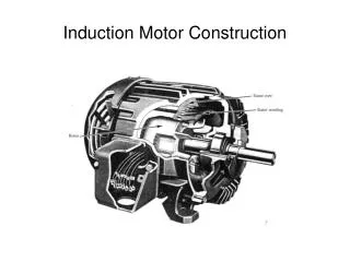
a 120o 120o c’ b’ c b a’ 120o Stator windings of practical machines are distributed Construction Coil sides span can be less than 180o – short-pitch or fractional-pitch or chorded winding If rotor is wound, its winding the same as stator Stator – 3-phase winding Rotor – squirrel cage / wound
Ni / 2 - /2 -/2 -Ni / 2 Single N turn coil carrying current i Spans 180o elec Permeability of iron >> o → all MMF drop appear in airgap a Construction a’
(3Nci)/2 (Nci)/2 -/2 - /2 Distributed winding – coils are distributed in several slots Nc for each slot Construction MMF closer to sinusoidal - less harmonic contents
The harmonics in the mmf can be further reduced by increasing the number of slots: e.g. winding of a phase are placed in 12 slots: Construction
In order to obtain a truly sinusoidal mmf in the airgap: Construction • the number of slots has to infinitely large • conductors in slots are sinusoidally distributed In practice, the number of slots are limited & it is a lot easier to place the same number of conductors in a slot
Phase a – sinusoidal distributed winding Air–gap mmf F() 2
i(t) t F() • Sinusoidal current excitation (with frequency s) in a phase produces space sinusoidal standing wave MMF • Sinusoidal winding for each phase produces space sinusoidal MMF and flux This is the excitation current which is sinusoidal with time
i(t) t F() • Sinusoidal current excitation (with frequency s) in a phase produces space sinusoidal standing wave MMF • Sinusoidal winding for each phase produces space sinusoidal MMF and flux 0 t = 0
Sinusoidal current excitation (with frequency s) in a phase produces space sinusoidal standing wave MMF • Sinusoidal winding for each phase produces space sinusoidal MMF and flux i(t) t t1 F() t = t1 2
Sinusoidal current excitation (with frequency s) in a phase produces space sinusoidal standing wave MMF • Sinusoidal winding for each phase produces space sinusoidal MMF and flux i(t) t t2 F() t = t2 2
Sinusoidal current excitation (with frequency s) in a phase produces space sinusoidal standing wave MMF • Sinusoidal winding for each phase produces space sinusoidal MMF and flux i(t) t t3 F() t = t3 2
Sinusoidal current excitation (with frequency s) in a phase produces space sinusoidal standing wave MMF • Sinusoidal winding for each phase produces space sinusoidal MMF and flux i(t) t t4 F() t = t4 2
Sinusoidal current excitation (with frequency s) in a phase produces space sinusoidal standing wave MMF • Sinusoidal winding for each phase produces space sinusoidal MMF and flux i(t) t t5 F() t = t5 2
Sinusoidal current excitation (with frequency s) in a phase produces space sinusoidal standing wave MMF • Sinusoidal winding for each phase produces space sinusoidal MMF and flux i(t) t t6 F() t = t6 2
Sinusoidal current excitation (with frequency s) in a phase produces space sinusoidal standing wave MMF • Sinusoidal winding for each phase produces space sinusoidal MMF and flux i(t) t t7 F() t = t7 2
Sinusoidal current excitation (with frequency s) in a phase produces space sinusoidal standing wave MMF • Sinusoidal winding for each phase produces space sinusoidal MMF and flux i(t) t t8 F() t = t8 2
Combination of 3 standing waves resulted in ROTATING MMF wave
Frequency of rotation is given by: p – number of poles f – supply frequency known as synchronous frequency
Emf in stator winding (known as back emf) Emf in rotor winding Rotor flux rotating at synchronous frequency • Rotating flux induced: Rotor current interact with flux to produce torque Rotor ALWAYS rotate at frequency less than synchronous, i.e. at slip speed:sl = s – r Ratio between slip speed and synchronous speed known as slip
Flux per pole: = 2 Bmaxl r Induced voltage Flux density distribution in airgap: Bmaxcos Sinusoidally distributed flux rotates at s and induced voltage in the phase coils Maximum flux links phase a when t = 0. No flux links phase a when t = 90o
Induced voltage a flux linkage of phase a a = N p cos(t) By Faraday’s law, induced voltage in a phase coil aa’ is Maximum flux links phase a when t = 0. No flux links phase a when t = 90o
Induced voltage In actual machine with distributed and short-pitch windinds induced voltage is LESS than this by a winding factor Kw
Stator phase voltage equation: Vs = Rs Is + j(2f)LlsIs + Eag Eag – airgap voltage or back emf (Erms derive previously) Eag = k f ag Rotor phase voltage equation: Er = Rr Ir + js(2f)Llr Er – induced emf in rotor circuit Er /s = (Rr / s) Ir + j(2f)Llr
Per–phase equivalent circuit Llr Ir Lls Rs + Vs – + Eag – + Er/s – Is Rr/s Lm Im Rs – stator winding resistance Rr – rotor winding resistance Lls – stator leakage inductance Llr – rotor leakage inductance Lm – mutual inductance s – slip
We know Eg and Er related by Where a is the winding turn ratio = N1/N2 The rotor parameters referred to stator are: • rotor voltage equation becomes • Eag = (Rr’ / s) Ir’ + j(2f)Llr’ Ir’
Is Lls Llr’ Ir’ Rs + Eag – + Vs – Rr’/s Lm Im Per–phase equivalent circuit Rs – stator winding resistance Rr’ – rotor winding resistance referred to stator Lls – stator leakage inductance Llr’ – rotor leakage inductance referred to stator Lm – mutual inductance Ir’ – rotor current referred to stator
Power and Torque Power is transferred from stator to rotor via air–gap, known as airgap power Lost in rotor winding Converted to mechanical power = (1–s)Pag= Pm
Power and Torque Mechanical power,Pm = Temr But, ss = s - r r = (1-s)s Pag = Tems Therefore torque is given by:
Power and Torque This torque expression is derived based on approximate equivalent circuit A more accurate method is to use Thevenin equivalent circuit:
Power and Torque Tem Pull out Torque (Tmax) Trated r 0 ratedsyn sTm s 1 0
Is Lls Llr’ Ir’ Rs + Eag – + Vs – Rr’/s Lm Im Steady state performance The steady state performance can be calculated from equivalent circuit, e.g. using Matlab
Is Lls Llr’ Ir’ Rs + Eag – + Vs – Rr’/s Lm Im Steady state performance e.g. 3–phase squirrel cage IM V = 460 V Rs= 0.25 Rr=0.2 Lr = Ls = 0.5/(2*pi*50) Lm=30/(2*pi*50) f = 50Hz p = 4