Download
1 / 23
250 likes | 516 Vues
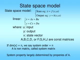
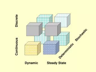
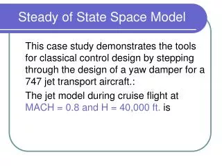
Steady of State Space Model. This case study demonstrates the tools for classical control design by stepping through the design of a yaw damper for a 747 jet transport aircraft.: The jet model during cruise flight at MACH = 0.8 and H = 40,000 ft. is. X’ = A .X+B.U & Y’ =C.X+D.U.

E N D
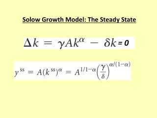
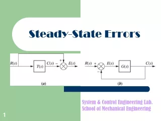
Steady of State Space Model This case study demonstrates the tools for classical control design by stepping through the design of a yaw damper for a 747 jet transport aircraft.: The jet model during cruise flight at MACH = 0.8 and H = 40,000 ft. is
X’ = A.X+B.U & Y’ =C.X+D.U A = [-0.0558 -0.9968 0.0802 0.0415 0.5980 -0.1150 -0.0318 0 -3.0500 0.3880 -0.4650 0 0 0.0805 1.0000 0];
X’ = A.X+B.U B = [ 0.0729 0.0000 -4.7500 0.00775 .15300 0.1430 0 0];
Y’ = C.X + D.U C = [0 1 0 0 0 0 0 1]; D = [0 0 0 0];
747 model The following commands specify this state-space model as an LTI object and attach names to the states, inputs, and outputs. states = {'beta' 'yaw' 'roll' 'phi'}; inputs = {'rudder' 'aileron'}; outputs = {'yaw' 'bank angle'}; sys = ss(A,B,C,D,'statename',states,... 'inputname',inputs,... 'outputname',outputs);
State Space Solution • You can display the LTI model sys by typing sys. MATLAB responds with: a =beta yaw roll phi beta -0.0558 -0.9968 0.0802 0.0415 yaw 0.598 -0.115 -0.0318 0 roll -3.05 0.388 -0.465 0 phi 0 0.0805 1 0
State Space Solution b = rudder aileron beta 0.0729 0 yaw -4.75 0.00775 roll 0.153 0.143 phi 0 0
State Space Solution c = beta yaw roll phi yaw 0 1 0 0 bank angle 0 0 0 1
State Space Solution d = rudder aileron yaw 0 0 bank angle 0 0
State Space Solution • Compute the open-loop eigenvalues and plot them in the s -plane. damp(sys) Eigenvalue Damping Freq. (rad/s) -7.28e-003 1.00e+000 7.28e-003 -5.63e-001 1.00e+000 5.63e-001 -3.29e-002 + 9.47e-001i 3.48e-002 9.47e-001 -3.29e-002 - 9.47e-001i 3.48e-002 9.47e-001
747 • The impulse response confirms that the system is lightly damped. But the time frame is much too long because the passengers and the pilot are more concerned about the behavior during the first few seconds rather than the first few minutes. Next look at the response over a smaller time frame of 20 seconds.
747 • Look at the plot from aileron (input 2) to bank angle (output 2). To show only this plot, right-click and choose I/O Selector, then click on the (2,2) entry. The I/O Selector should look like this.
747 • The aircraft is oscillating around a nonzero bank angle. Thus, the aircraft is turning in response to an aileron impulse. This behavior will prove important later in this case study. Typically, yaw dampers are designed using the yaw rate as sensed output and the rudder as control input. Look at the corresponding frequency response.
bode(sys11) From this Bode diagram, you can see that the rudder has significant effect around the lightly damped Dutch roll mode (that is, near rad/sec).
This is the root locus for negative feedback and shows that the system goes unstable almost immediately. If, instead, you use positive feedback, you may be able to keep the system stable. • rlocus(-sys11) • sgrid
Damping Ratio • This looks better. By using simple feedback, you can achieve a damping ratio of . Click on the blue curve and move the data marker to track the gain and damping values. To achieve a 0.45 damping ratio, the gain should be about 2.85. This figure shows the data marker with similar values