
SlideServe
Menu
Préférences
© SlideServe · v2026

Induction Motor Construction

joey avatar
15 diapositives · 709 Views · Oct 15, 2014

Induction Motor Construction. Squirrel-Cage Rotor. Another Squirrel-Cage Rotor. Wound-Rotor. Stator Coils for a 2-pole 3-  induction motor. Connection diagram. Stator Coils for a 2-pole 3-  induction motor. Coil Span and distance between center lines.
Induction Motor Construction - slide 1
01 / 15Induction Motor Construction
1 / 17

Télécharger la présentation

Induction Motor Construction
Une image / un lien ci-dessous est fourni (tel quel) pour télécharger la présentation

Politique de téléchargement : le contenu du site vous est fourni TEL QUEL pour votre information et votre usage personnel ; il ne peut être vendu, concédé sous licence ni partagé sur d’autres sites sans l’accord de son auteur.Le contenu vous est fourni TEL QUEL, pour votre information et votre usage personnel uniquement. Téléchargez la présentation en cliquant sur ce lien. Lors du téléchargement, si vous ne parvenez pas à télécharger une présentation, l’éditeur a peut-être supprimé le fichier de son serveur.Pendant le téléchargement, si vous ne parvenez pas à obtenir une présentation, le fichier a peut-être été supprimé par l’éditeur.

F I N

Plus de contenu associé

Transcription de la présentation
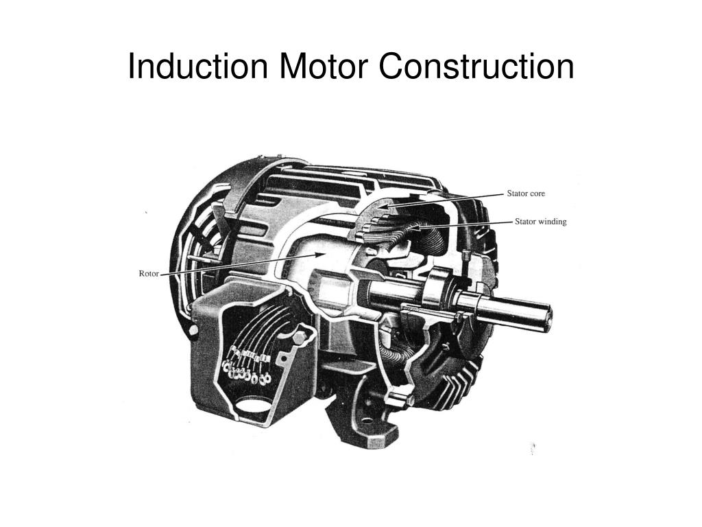
  1. Induction Motor Construction

  2. Squirrel-Cage Rotor

  3. Another Squirrel-Cage Rotor

  4. Wound-Rotor

  5. Stator Coils for a 2-pole 3- induction motor Connection diagram

  6. Stator Coils for a 2-pole 3- induction motor

  7. Coil Span and distance between center lines Coil Span = Stator circumference / # of stator poles Distance between center lines = 120/ # of pole pairs For a 2-pole machine, Coil Span = 360/2 = 180 Center line distance = 120

  8. Coil Span and distance between center lines Coil Span = Stator circumference / # of stator poles Distance between center lines = 120/ # of pole pairs For a 4-pole machine, Coil Span = 360/4 = 90 Center line distance = 60

  9. Synchronous Speed • ns = synchronous speed (r/min) • the speed of the rotating magnetic flux • ns = fs/(P /2) (r/s) • where • fs = frequency of the 3- supply • ns = synchronous speed • P = number of poles formed by the stator winding • ns = 120(fs)/P (r/min)

  10. Slip • ns = synchronous speed of the rotating flux • nr = speed of the rotor • slip speed = n = ns-nr • slip = s = (ns-nr) / ns = per-unit slip • % slip = s x 100% • solving for nr , • nr = ns(1-s)

  11. Effect of slip on rotor frequency • frequency of the voltage induced in the rotor, fr • fr = Pn/120, where • P = the number of stator poles • n = the slip speed (r/min) • fr = rotor frequency (Hz) = P(ns – nr)/120 • fr = P(sns)/120 = s(Pns/120) = proportional to s!

  12. “Blocked rotor” condition (nr=0) • s = (ns–nr)/ns = (ns-0)/ns = 1 • fr = s(Pns/120) = Pns/120 = same as source • fr = fBR = fstator • In general, fr = sfBR

  13. Effect of slip on rotor voltage • For a squirrel-cage rotor, • >Er = 4.44Nfrmax = 4.44NsfBRmax • at blocked rotor, s=1 • >EBR = 4.44NfBRmax => Er = sEBR

  14. Consequent-Pole Motor 4-pole machine 8-pole machine

  15. Winding Connections Switch “up”, coils 1 & 3 have opposite polarity to coils 2 & 4. Looks like a 4-pole machine. (Fast) Switch “down”, all coils have the same polarity. Looks like an 8-pole machine. (Slow)