Download
1 / 15
150 likes | 224 Vues
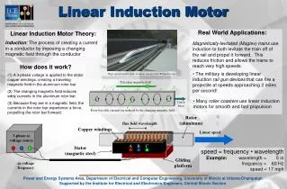
Understand and analyze an induction motor model through circuit analysis. Learn to compute power, torque, losses, and more using the per-phase circuit model with given motor parameters.

E N D
Lesson13_et332b.pptx ET 332b Ac Motors, Generators and Power Systems Lesson 13 Induction Motor Model Example
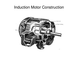
Lesson13_et332b.pptx Learning Objectives • After this presentation you will be able to: • Draw the per phase circuit model of an induction motor • Correctly place motor parameters on the circuit model • Reduce the circuit model and solve of stator and rotor currents • Compute the motor power and losses • Compute motor torques
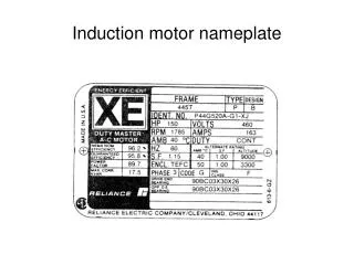
Lesson13_et332b.pptx Example 13-1:A 60 Hz, 15 HP, 460 V, 4-pole wye connected induction spins a mechanical load at 1778 RPM. The motor parameters given in ohms refered to the stator are: R1 = 0.18 R2 = 0.20 X1 = 1.15 X2 = 1.23 XM = 40 Rfe= 317 Total mechanical power losses (friction, windage and stray) are 170 W Find: a.) the motor slip; b.) the motor line current; c.) the apparent power the motor draws from the system; d.) active power drawn by the motor; e.) motor power factor; f.) total electric power losses of motor; g.) shaft power and torque; h.) efficiency Use per phase circuit model and circuit analysis to find these quantities
Lesson13_et332b.pptx Example 13-1 Solution (1) Per phase circuit model R1=0.18 Ω X2=1.23 Ω X1=1.15 Ω R2/s=0.2/s Ω Rfe=317 Ω xm=40 Ω f = 60 Hz Number of poles : P=4 nr = 1778 RPM Pfw+Pstray = 170 W
Lesson13_et332b.pptx Example 13-1 Solution (2) Find the motor slip
Lesson13_et332b.pptx Example 13-1 Solution (3) Zp
Lesson13_et332b.pptx Example 13-1 Solution (4) Find Zin to find the phase current in the stator
Lesson13_et332b.pptx Example 13-1 Solution (5)
Lesson13_et332b.pptx Example 13-1 Solution (6) Find the power factor and the total power losses
Lesson13_et332b.pptx Example 13-1 Solution (7) Compute the rotor induced voltage Value almost equal to phase voltage Find the rotor current from the value of E2 and the rotor impedance, Z2 Power loss formula
Lesson13_et332b.pptx Example 13-1 Solution (8)
Lesson13_et332b.pptx Example 13-1 Solution (9)
Lesson13_et332b.pptx Approximate Equivalent Circuit Approximate Equivalent Circuit - move magnetizing branch Stator impedance is usually small so there is little voltage drop across Z1
Lesson13_et332b.pptx Approximate Equivalent Circuit Adjusting the values of R1 and R2 affect TD Above equation derived from approximate equivalent circuit TD proportional to V2 Reducing V reduces torques
Lesson13_et332b.pptx ET 332b Ac Motors, Generators and Power Systems End Lesson 13 Induction Motor Model Example