Download
1 / 19
230 likes | 322 Vues
Learn about variable speed control of three-phase induction motor using Direct Torque Control (DTC) with a six-switch inverter. Explore the advantages of this proposed method over existing strategies. Discover the project methodology using MATLAB/Simulink and DSP Builder.

E N D
FPGA DESIGN APPROACH OF DIGITAL CONTROL OF THREE-PHASE INDUCTION MOTOR By: Prof Dr. Cesar da Costa
OBJECTIVE • Variable speed control of three phase induction motor using a six switch inverter by Direct Torque Control (DTC).
DISADVANTAGES OF EXISTING METHOD • Harmonic content in motor current increase at low speed; • The machine saturates at light loads due high V/f ratio; • These effects overheat the machine at low speed; • Smooth speed control of induction motor is not possible; • The cost of the method is high but less efficient.
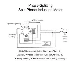
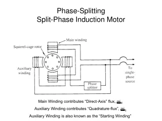
PROPOSED METHOD • The speed control of induction motor is done using Direct Torque Control (DTC) with six switch three phase inverter; • The switching technique used is space vector modulation technique; • The two phases are connected to the two legs of the inverter, while the third phase is connected to the mid point of the dc-bus voltage.
BLOCK DIAGRAM Structure of direct torque control proposed.
Direct Torque Control • Stator flux linkage is estimated by integrating the stator voltages; • Torque is estimated as a cross product of estimated stator flux linkage vector and measured motor current vector; • The estimated flux magnitude and torque are then compared with their reference values.
INVERTER (VSI) Scheme of Voltage Source Inverter (VSI).
. SPACE VECTOR MODULATION The space sector N is obtained from the angle between the stacionary reference and the stator flux.
DTC Strategy Simulation DSP Builder
Simulation Results (b) (a) Stator flux estimated (a), and Electromagnetic torque estimated by the proposed DTC (b).
Simulation Results (a) (b) Three-phase stator currents (a), and Motor Speed by the proposed DTC algorithm (b).
CONCLUSIONS • The implementation, which proved that the DTC strategy, was accomplished using the combination of a MATLAB/Simulink and DSP Builder software. • This project addressed a way of structuring and simulating a DTC algorithm. The target technology was FPGAs, which have been growing steadily and has been taking up space in the industrial market worldwide.