Download
1 / 4
40 likes | 62 Vues
In this paper a three phase induction motor controller for a photovoltaic powered water pump without the use of chemical storage element is presented. The use of a three phase induction motor is a better solution to the dc motor water pumping system. This system is use to achieve a more efficient, reliable, maintenance free, and cheaper solution than that use dc motors or low voltage synchronous motors. The developed system is based on a non inverting buckboost converter and a full bridge three phase inverter. Maximum Power Point Tracking MPPT algorithm has been developed and implemented to maximize the use of solar power generated at any given instant. By using MATLAB Simulink model is implemented. The system is expected to have a high lifetime due to the inexistence of storage element. As a result, the system is a economical solution to deliver water to household, industrial and agricultural activities which require water supply. Swati Killedar | Dr. S. N. Patil | Prof. A. P. Kinge "Design and Simulation of MPPT Algorithm for Three Phase Induction Motor Solar Water Pump" Published in International Journal of Trend in Scientific Research and Development (ijtsrd), ISSN: 2456-6470, Volume-2 | Issue-2 , February 2018, URL: https://www.ijtsrd.com/papers/ijtsrd9682.pdf Paper URL: http://www.ijtsrd.com/engineering/electrical-engineering/9682/design-and-simulation-of-mppt-algorithm-for-three-phase-induction-motor-solar-water-pump/swati-killedar<br>

E N D
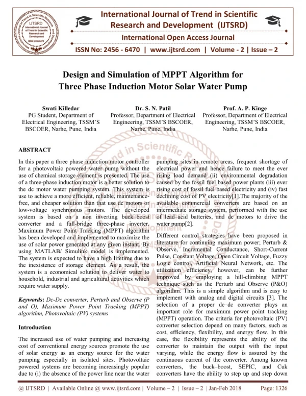
International Research Research and Development (IJTSRD) International Open Access Journal imulation of MPPT Algorithm for Three Phase Induction Motor Solar Water Pump Three Phase Induction Motor Solar Water Pump International Journal of Trend in Scientific Scientific (IJTSRD) International Open Access Journal ISSN No: 2456 ISSN No: 2456 - 6470 | www.ijtsrd.com | Volume www.ijtsrd.com | Volume - 2 | Issue – 2 Design and Simulation of MPPT Algorithm for Three Phase Induction Motor Solar Water Pump imulation of MPPT Algorithm for Swati Killedar PG Student, Department of Electrical Engineering, TSSM’S BSCOER, Narhe, Pune, India Dr. S. N. Patil Prof. A. P. Kinge Professor, Department of Electrical Engineering, TSSM’S BSCOER, Prof. A. P. Kinge Professor, Department of Electrical Engineering, TSSM’S BSCOER, Narhe, Pune, India Narhe, Pune, India Professor, Department of Electrical Engineering, TSSM’S BSCOER, Engineering, TSSM’S BSCOER, Narhe, Pune, India Professor, Department of Electrical ABSTRACT In this paper a three phase induction motor controller for a photovoltaic powered water pump without the use of chemical storage element is presented. The use of a three-phase induction motor is a better solution to the dc motor water pumping system. This use to achieve a more efficient, reliable, maintenance free, and cheaper solution than that use dc motors or low-voltage synchronous motors. The developed system is based on a non inverting buck converter and a full-bridge three-phase inver Maximum Power Point Tracking (MPPT) algorithm has been developed and implemented to maximize the use of solar power generated at any given instant. By using MATLAB/ Simulink model is implemented. The system is expected to have a high lifetime due to the inexistence of storage element. As a result, the system is a economical solution to deliver water to household, industrial and agricultural activities which require water supply. Keywords: Dc-Dc converter, Perturb and Observe (P and O), Maximum Power Point Tracking (MPPT) algorithm, Photovoltaic (PV) systems Introduction In this paper a three phase induction motor controller for a photovoltaic powered water pump without the use of chemical storage element is presented. The use phase induction motor is a better solution to the dc motor water pumping system. This system is use to achieve a more efficient, reliable, maintenance- free, and cheaper solution than that use dc motors or voltage synchronous motors. The developed system is based on a non inverting buck–boost pumping sites in remote areas, frequent shortage of er and hence failure to meet the ever rising load demand (ii) environmental degradation caused by the fossil fuel based power plants (iii) ever rising cost of fossil fuel based electricity and (iv) fast declining cost of PV electricity[1].The majority of the available commercial converters are based on an intermediate storage system, performed with the use acid batteries, and dc motors to drive the pumping sites in remote areas, frequent shortage of electrical power and hence failure to meet the ever rising load demand (ii) environmental degradation caused by the fossil fuel based power plants (iii) ever rising cost of fossil fuel based electricity and (iv) fast declining cost of PV electricity[1].The majority of t available commercial converters are based on an intermediate storage system, performed with the use of lead–acid batteries, and dc motors to drive the water pump[2]. phase inverter. Maximum Power Point Tracking (MPPT) algorithm has been developed and implemented to maximize the use of solar power generated at any given instant. By using MATLAB/ Simulink model is implemented. The system is expected to have a high lifetime due to he inexistence of storage element. As a result, the system is a economical solution to deliver water to household, industrial and agricultural activities which Different control strategies have been proposed in literature for continuing maximum power; Perturb & Observe, Incremental Conductance, Short-Current Pulse, Constant Voltage, Open Circuit Voltage, Fuzzy Logic control, Artificial Neural Network, etc. The ilization efficiency, however, can be further improved by employing a hill-climbing MPPT technique such as the Perturb and Observe (P&O) algorithm. This is a simple algorithm and is easy to implement with analog and digital circuits [3]. The Different control strategies have been proposed in literature for continuing maximum power; Perturb & Observe, Incremental Conductance, Short Pulse, Constant Voltage, Open Circuit Voltage, Fuzzy Logic control, Artificial Neural Network, etc. The utilization efficiency, however, can be further improved by employing a hill technique such as the Perturb and Observe (P&O) algorithm. This is a simple algorithm and is easy to implement with analog and digital circuits [3]. The selection of a proper dc–dc converter plays an important role for maximum power point tracking (MPPT) operation. The criteria for photovoltaic (PV) converter selection depend on many factors, such as cost, efficiency, flexibility, and energy flow. In this case, the flexibility represents the ability of the converter to maintain the output with the input varying, while the energy flow is assured by the continuous current of the converter. Among known converters, the buck–boost, SEPIC, and Cuk converters have the ability to step up and step down Dc converter, Perturb and Observe (P and O), Maximum Power Point Tracking (MPPT) dc converter plays an important role for maximum power point tracking (MPPT) operation. The criteria for photovoltaic (PV) converter selection depend on many factors, such as cost, efficiency, flexibility, and energy flow. In this ibility represents the ability of the converter to maintain the output with the input varying, while the energy flow is assured by the continuous current of the converter. Among known boost, SEPIC, and Cuk The increased use of water pumping and increasing cost of conventional energy sources promote the use of solar energy as an energy source for the water pumping especially in isolated sites. Photovoltaic powered systems are becoming increasingly popular due to (i) the absence of the power line near the water due to (i) the absence of the power line near the water The increased use of water pumping and increasing cost of conventional energy sources promote the use s an energy source for the water pumping especially in isolated sites. Photovoltaic powered systems are becoming increasingly popular o step up and step down @ IJTSRD | Available Online @ www.ijtsrd.com @ IJTSRD | Available Online @ www.ijtsrd.com | Volume – 2 | Issue – 2 | Jan-Feb 2018 Feb 2018 Page: 1326
International Journal of Trend in Scientific Research and Development (IJTSRD) ISSN: 2456-6470 the input voltage. There are many factors that can be considered for proposing the DC-DC Converters, hence non inverting buck–boost converter is better [4]. PV pumping systems without battery can provide a cost effective use of solar energy. Nowadays, due to development of IM drive systems it is possible to use a more robust and less expensive motor for photovoltaic pumping application [5] [6]. Following are the features of proposed topology: high efficiency due to the low energy available; low cost; no specific training needed to operate the system; minimum amount of maintenance possible and high life span comparable to the usable life of 20 years of a PV panel. Block Diagram DC –DC Converter Fig. 2 Diagram for a basic non inverting buck boost converter Figure 1 shows the simplified block diagram of proposed PV water pumping system. The energy produced by the PV panel is fed to the motor through a converter with two power stages: a dc-dc converter and dc-ac three-phase inverter. DC-DC converter is used to boost the voltage of the panels and a dc/ac three-phase inverter to convert the dc voltage to three- phase ac voltage. The inverter is based on a classic topology and uses a sinusoidal pulse width modulation (PWM) The use of this PWM strategy is to improve the output voltage level as compared to sinusoidal PWM modulation. MPPT algorithm is implemented through dc-dc converter. Pulse width modulation signal is given to three phase inverter and it continuously check speed of induction motor, and generate required signal to drive the water pump. All dc-dc converters operate by rapidly turning on and off of two switches, generally with a high frequency pulse. Diagram of non inverting buck boost converter is as shown in fig.2, when the pulse is high/the switch Q1 and Q2 is on, inductor L is charged by the input voltage. When the pulse is low/ both the switch is off, the energy stored in inductor is discharged to the capacitor. The greater the percentage of time (duty cycle) the pulse is low, the greater the output will be. This is because the longer the inductors charge, the greater their voltage will be. The converter will fail if capacitors will not be charge because of pulse being too long. This dc-dc converter allowing the electrical voltage at its output to be greater than, less than, or equal to that at its input; the output of the non inverting buck boost converter is controlled by the duty cycle of the control switch. Step up or step down the voltage of this buck boost converter depends primarily on the duty cycle and the parasitic elements in the circuit. The output of an ideal buck boost converter is given by (1) ⁄ − 1)V? (1) V?= (D 1 Where, D is the duty ratio. And duty ratio is defined as the ratio of the ON period of switch to the total switching time period. Fig. 1 Block diagram of the proposed system. This becomes ??? ???????? (2) D = @ IJTSRD | Available Online @ www.ijtsrd.com | Volume – 2 | Issue – 2 | Jan-Feb 2018 Page: 1327
International Journal of Trend in Scientific Research and Development (IJTSRD) ISSN: 2456-6470 In theory, the larger the inductors are the better the circuit will operate and reduce the ripple. However, larger inductors are more expensive and have a larger internal resistance. This greater internal resistance will make the converter less efficient. Creating the best converter requires choosing inductors that are just large enough to keep the voltage and current ripple at an acceptable amount. Simulink Design The most important decision in this process is the choosing of the solar cells. Silicon was the material of the first solar cells and nowadays is mostly used in terrestrial settings due to its low production cost and low efficiency. Terrestrial applications generally value cost over surface area consumed so silicon is a great fit. These cells generally range from 12%- 18% efficient and come in two crystal types, mono crystalline and polycrystalline [1].The figure 3 represents the circuit used in simulink model. The fundamental magnitude of the output inverter can be controlled to be constant by exercising control within the inverter itself that is external circuit is not required. The most efficient method of doing this is by Pulse Width Modulation (PWM) control used within inverter. In this scheme the inverter is fed by a fixed controlled ac voltage. ???(???)???? (???(???)????)∆??? (3) L = Where, V??(???)=Minimum input voltage V???= Output voltage f= Switching frequency ∆I? = Selected inductor ripple current P and O MPPT Algorithm Perturb and Observe MPPT algorithm is used to achieve maximum power point. Maximum power point tracker uses different control circuits to search for this point and allow the converter circuit to extract the maximum power available from cell. In the current method the controller adjusts the voltage from array and measures power, if the power increases, further adjustments in the direction are tried until there is no increase of power. This is called P and O method. It is the most commonly used MPPT method Because of ease of implementation. PV modules output power curve as a function of voltage (P-V curve), at the constant irradiance and the constant module temperature, assuming the PV module is operating at a point which is away from the MPP. From the P–V characteristics shown in fig.5 it can be visualized that the operating voltage of the PV module is perturbed by a small increment, and the resulting change of power, P is observed. If the P is positive, then the operating point has moved toward the MPP. Thus, further voltage adjustments in the same direction should move the operating point toward the MPP. Direction of perturbation should be reversed if the P is negative as the operating point has moved away from the MPP. The duty cycle and the PV voltage (V??) are inversely proportional to each other, i.e., an increase in duty cycle causes the (V??) to decrease and vice versa. Fig. 3 Circuit used in simulink model Result and Discussion Figure 4 shows I-V Characteristics of solar panel with different irradiance level. For any operating conditions, cells have a single operating point where the values of current and voltage of cell results in maximum power output. Figure 5 shows P-V Characteristics of solar panel with different irradiance level. In a PV curve of solar panel there is an optimum operating point such that panel delivers maximum power to load. Table I shows the efficiency of converter after implementation of MPPT algorithm with different solar irradiation. Due to implementation of MPPT @ IJTSRD | Available Online @ www.ijtsrd.com | Volume – 2 | Issue – 2 | Jan-Feb 2018 Page: 1328
International Journal of Trend in Scientific Research and Development (IJTSRD) ISSN: 2456-6470 algorithm efficiency of system is considerably increases. Conclusion This paper presents the simulation of solar powered induction motor water pumping system without the use of chemical storage elements. The simulink model can be used to relate input quantities like solar array voltage, current to outputs like speed, torque. The simulation of integrated system is presented the results can be used to select the ratings of the various components. The simulation results suggest that the proposed solution could be a viable option for PV water pumping system. And it is economical solution having low cost, high efficiency, and robustness. Fig. 4 I-V characteristics of solar panel References 1)M. Chunting, M. B. R. Correa, and J. O. P. Pinto, “The IEEE 2011 international future energy challenge—Request for proposals,” in Proc. IFEC, 2010, pp. 1–24. 2)Author H. Harsono, “Photovoltaic water pump system, Ph.D. dissertation”, Dept. Intell. Mech. Syst. Eng., Faculty Kochi Univ. Technol., Kochi, Japan, Aug. 2003. 3)M. A. Vitorino and M. B. R. Correa, “High performance photovoltaic pumping system using induction motor”, in Proc. Brazilian Power Electron. Conf., 2009, pp. 797804. Fig. 5 P-V characteristics of solar panel 4)Mohammed A. Elgendy, Bashar Zahawi and David J. Atkinson, “Assessment of Perturb and Observe MPPT Algorithm Techniques for PV Pumping Applications”, IEEE Transactions On Sustainable Energy, Vol. 3, No. 1, January 2012. Implementation TABLE implementation of MPPT algorithm I: Efficiency of converter after Irradiance (w/m2) Input Power (watt) Output Power (watt) Efficiency 5)Subramanya Bhat and H N Nagaraja, "A Novel DSP Based Non Inverting Buck Boost Converter For PV System", IEEE International Conference On SPICES, Feb 2015. (%) 1000 1479 1389 93.9 6)Joao Victor Mapurunga Caracas and Guilherme de Carvalho Farias, “Implementation of a High Efficiency, High-Lifetime, Converter for an Autonomous Photovoltaic Water Pumping System”, IEEE transactions on industry applications, vol. 50, no. 1, January/February 2014. 800 1435 1346 93.8 and Low-Cost 600 1342 1255 93.5 400 1238 1148 92.7 200 1150 1050 91.3 @ IJTSRD | Available Online @ www.ijtsrd.com | Volume – 2 | Issue – 2 | Jan-Feb 2018 Page: 1329