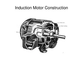
Download

1 / 30
330 likes | 877 Vues
INDUCTION MOTOR Scalar Control (squirrel cage). MEP 1523 ELECTRIC DRIVES. Scalar control of induction machine: Control of induction machine based on steady-state model (per phase SS equivalent circuit):. I s. I r ’. L ls. L lr ’. R s. + V s –. + E ag –. R r ’ /s. L m. I m.

E N D
INDUCTION MOTORScalar Control(squirrel cage) MEP 1523 ELECTRIC DRIVES
Scalar control of induction machine:Control of induction machine based on steady-state model (per phase SS equivalent circuit): Is Ir’ Lls Llr’ Rs + Vs – + Eag – Rr’/s Lm Im
Intersection point (Te=TL) determines the steady –state speed Te TL rated rotor sm Scalar control of induction machine Te Pull out Torque (Tmax) Trated r s s
Variable voltage (amplitude), variable frequency Using power electronics converter Operated at low slip frequency Pole changing Synchronous speed change with no. of poles Discrete step change in speed Variable voltage (amplitude), frequency fixed E.g. using transformer or triac Slip becomes high as voltage reduced – low efficiency Scalar control of induction machine Given a load T– characteristic, the steady-state speed can be changed by altering the T– of the motor:
Variable voltage, fixed frequency e.g. 3–phase squirrel cage IM V = 460 V Rs= 0.25 Rr=0.2 Lr = Ls = 0.5/(2*pi*50) Lm=30/(2*pi*50) f = 50Hz p = 4 Lower speed slip higher Low efficiency at low speed
Variable voltage, variable frequency Constant V/f operation At low slip
Variable voltage, variable frequency – Constant V/f If Φagis constant Te α slip frequency
Variable voltage, variable frequency – Constant V/f How do we make constant ? Approximates constant air-gap flux when Eag is large Eag = k f ag = constant Speed is adjusted by varying f - maintaining V/f to approximate constant air-gap flux
Variable voltage, variable frequency – Constant V/f Characteristic with constant
Variable voltage, variable frequency Constant constant V/f Vs Vrated Constant slope frated f
rate limiter is needed to ensure the slip change within allowable range (e.g. rated value) Variable voltage, variable frequency Constant V/f – open-loop Rectifier VSI 3-phase supply IM C f Pulse Width Modulator Ramp V + s*
Variable voltage, variable frequency Constant V/f – open-loop Simulation example: 415V, 50Hz, 4 pole, Rs = 0.25, Rr = 0.2, Lr=Ls= 0.0971 H, Lm = 0.0955, J = 0.046 kgm2 , Load: k2
Variable voltage, variable frequency Constant V/f – open-loop Simulation example: 415V, 50Hz, 4 pole, Rs = 0.25, Rr = 0.2, Lr=Ls= 0.0971 H, Lm = 0.0955, J = 0.046 kgm2 , Load: k2 constant_vhz_withoutBoost/Signal Builder : Group 1 Signal 1 50 40 30 20 10 0 0 0.5 1 1.5 2 2.5 3 3.5 Time (sec)
Variable voltage, variable frequency Constant V/f – open-loop Simulation example: 415V, 50Hz, 4 pole, Rs = 0.25, Rr = 0.2, Lr=Ls= 0.0971 H, Lm = 0.0955, J = 0.046 kgm2 , Load: k2
Variable voltage, variable frequency Constant V/f – open-loop Simulation example: 415V, 50Hz, 4 pole, Rs = 0.25, Rr = 0.2, Lr=Ls= 0.0971 H, Lm = 0.0955, J = 0.046 kgm2 , Load: k2 With almost no rate limiter
Variable voltage, variable frequency Constant V/f – open-loop Simulation example: 415V, 50Hz, 4 pole, Rs = 0.25, Rr = 0.2, Lr=Ls= 0.0971 H, Lm = 0.0955, J = 0.046 kgm2 , Load: k2 With 628 rad/s2
Variable voltage, variable frequency Constant V/f – open-loop low speed problems Problems with open-loop constant V/f At low speed, voltage drop across stator impedance is significant compared to airgap voltage - poor torque capability at low speed Solution: (i) Voltage boost at low frequency (ii) Maintain Im constant stator current control
Variable voltage, variable frequency Constant V/f – open-loop low speed problems (i) voltage boost • Torque deteriorate at low frequency – hence compensation commonly performed at low frequency • In order to truly compensate need to measure stator current – seldom performed
Variable voltage, variable frequency Constant V/f – open-loop low speed problems (i) voltage boost With voltage boost of Irated*Rs • Torque deteriorate at low frequency – hence compensation commonly performed at low frequency • In order to truly compensate need to measure stator current – seldom performed
Variable voltage, variable frequency Constant V/f – open-loop low speed problems (i) voltage boost Voltage boost at low frequency Vrated Linear offset Non-linear offset – varies with Is Boost frated
Variable voltage, variable frequency Constant V/f – open-loop low speed problems (i) voltage boost Idc Rectifier + Vdc - VSI 3-phase supply IM C f Pulse Width Modulator Ramp + V s* + Vboost
Variable voltage, variable frequency Constant V/f – open-loop low speed problems (i) Constant Im ag, constant → Eag/f , constant → Im, constant (rated) Controlled to maintain Im at rated Is Lls Llr’ Ir’ Rs + Vs – + Eag – Lm Rr’/s maintain at rated Im
Variable voltage, variable frequency Constant V/f – open-loop low speed problems (i) Constant Im From per-phase equivalent circuit, • Current is controlled using current-controlled VSI • The problem of stator impedance drop is solved • Dependent on rotor parameters – sensitive to parameter variation
Variable voltage, variable frequency Constant V/f – open-loop low speed problems (i) Constant Im VSI 3-phase supply Rectifier IM C Current controller Tacho slip |Is| * + PI - + s r Current reference generator +
Variable voltage, variable frequency Constant V/f Problems with open-loop constant V/f Poor speed regulation Solution: (i) Slip compensation (ii) Closed-loop control
Variable voltage, variable frequency Constant V/f – poor speed regulation: (i) slip compensation Motor characteristic AFTER slip compensation T Tload Motor characteristic BEFORE slip compensation T2 T1 ωs2*=ωs1*+ωslip1 ωs1* ωr (rad/s) ωslip1 ωslip1 ωr1 ωr2≈ωs1*
Variable voltage, variable frequency Constant V/f – poor speed regulation: (i) slip compensation Idc Rectifier + Vdc - VSI 3-phase supply IM C f Pulse Width Modulator Ramp + V + s* + + Vboost Slip speed calculator Vdc Idc
Idc INV + Vdc STATOR ROTOR Pmotor,in Pair-gap Stator Core losses Stator Copper lossess Variable voltage, variable frequency Constant V/f – poor speed regulation: (i) slip compensation How is the slip frequency calculated ? Pmotor,in= Pdc – Pinv,losses Pdc= VdcIdc
Variable voltage, variable frequency Constant V/f – poor speed regulation: (i) slip compensation How is the slip frequency calculated ? Pair-gapc = Tesyn Te = Pair-gap/syn For constant V/f control,
Variable voltage, variable frequency Constant V/f – poor speed regulation: (i) closed-loop speed • Require speed encoder • Increase complexity