Download

1 / 52
520 likes | 833 Vues
CAP 2 MOTOR & SOFT STARTER January 10 TH 2013. SQUIRREL CAGE MOTORS. Induction motor (asynchronous or squirrel cage), are composed of two main parts: The stator . The rotor , fixed to a shaft. » Motor section. » Motor section. INDUCTION MOTORS.

E N D
CAP 2 MOTOR & SOFT STARTERJanuary 10TH 2013
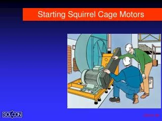
SQUIRREL CAGE MOTORS • Induction motor (asynchronous or squirrel cage), are composed of two main parts: • The stator. • The rotor , fixed to a shaft. » Motor section » Motor section
INDUCTIONMOTORS • The rotor is built using bars which are short-circuited at both ends. It is this rotor construction that gives the squirrel cagemotor its name. » Motor structure
INDUCTION MOTORS Connecting the stator to a three-phase power supply, generates a rotating magnetic field in the stator (flux). This is due to: • The physical distribution of stator coils: 3 coils separated 120º physically. • The current in these 3 coils has 120º electrical displacement. » Flux lines
ROTATING FIELD INDUCTIONMOTORS • Flux lines (arrows) induce currents into the rotor bars. • The interaction of the magnetic fields generated in the stator and rotor create a force that is capable of creating torque. It is this torque that causes the rotor to rotate. • ns : Synchronous speed. • f: frequency (Hz) • p : Motor poles • Pm: Shaft power (W) • Г: Torque (N·m) • J: Moment of Inertia (kg·m2) • α : Angular acceleration (rad/s2) • ω : Angular velocity (rad/s) • Pe: Electric Power (W) • U: Voltage (V) • I: Absorbed Current (A) » Rotating field
MOTOR EQUIVALENT CIRCUIT: TRANSFORMER • The equivalent motor circuit can be explained like a transformer. IM: Magnetizing current. “Imaginary” current which flows in stator. Responsible of motor flux. IR: Rotor current. “Real” current which flows in rotor, torque generator. Increases with motor load.
MOTOR EQUIVALENT CIRCUIT: TRANSFORMER • Controlling the voltage applied to the stator (E1) it is possible to control magnetizing current (IM) and consequently the flux. • When motor speed increases, slip (S) decreases andIr decreases
MOTOR EQUIVALENT CIRCUIT: ELECTRIC CIRCUIT PER PHASE • Equivalent circuit of a motor for each phase can be simplified as follows: Magnetic Inductance Load Resistor. If S then R • Motor slip is speed function:
MOTOR EQUIVALENT CIRCUIT: ELECTRIC CIRCUIT PER PHASE • Upon the instant of start up instant the motor acts like a transformer with the secondary in short circuited. Ir increases because it is like a short-circuit current. • As soon as rotor speed increasescosφR improves and as a result Irdecreases.
CURRENT- DIRECT ON LINE START • The motor cannot reach full synchronous speed as it will lose the capability of generating torque. • Nominal current is reached at approx. 95% - 98% synchronous speed.
INPUT VOLTAGE REDUCTION • It is possible to demonstrate that: • If the main voltage (E1) changes, then the resulting torque (T) is quadratic in relationship to the voltage. • Upon start up, the instant torque is proportional to the square of the main voltage.
EXTENDED START UP SYSTEMS • Existing different motor starting methods: • Direct on line (DOL) • Star-delta (Y/∆) • Primary resistance • Secondary resistance (wound rotor motor). • Basically all of them present problems. • Excessive torque applied • High inrush current • Wiring complexity
MOTOR START UP PROBLEMS • EXCESSIVE TORQUE APPLIED: Even if resistant torque is low, during the start strong oscillations appear as the speed increases. This is basically an uncontrolled start. • Disadvantages: • Mechanical Shocks. • Belt slip. • Transmission stress. • Over-pressure.
MOTOR START UP PROBLEMS • HIGH OVER-CURRENT: Typical current at start up can be between 7 and 10 times nominal current. That is due to maximum slip being present at this moment, and the motor acting like a transformer with a short-circuit in the secondary. • Disadvantages: • Strong voltage drops at main lines with low capacity. • Contactors over-sizing. • Correct calculation for fuses..
DIRECT ON LINE STARTING CONNECTION • PURPOSE: Motor functions since the very beginning at nominal values
DIRECT ON LINE START • RESULT: High start up current. Uncontrolled start up.
STAR – DELTA START CONNECTION • PURPOSE: To reduce instantaneous current on start up. This also means a torque reduction.
STAR – DELTA START CONNECTION • MOTOR: It is necessary to have a motor with all stator coils accessible and configured for a star – delta connection.
START – DELTA START UP • RESULT: Over-current at re-connection instant. Power supply loss. Uncontrolled start up
OBJECTIVES • PERFECT MECHANICAL START UP: To overcome initial torque slowly. • TO CONTROL MOTOR TORQUE: In order to control motor acceleration. • TO CONTROL STOP MODE: Deceleration in a controlled manner. • MAINTENANCE: Less maintenance operation in installations. • TO LIMIT STARTING CURRENT: Eliminating disturbance to mains supply lines. • SANCTIONS: To avoid penalties from supply authorities s due to current peaks caused by traditional starting methods. It is possible to save on electricity bills.
SOFTSTARTERS OUTLINES • Soft starter principle is known as PHASE CONTROL. • By controlling the thyristortrigger it is possible to control the RMS voltage applied to the load. • Using an inverse parallel thyristor connection it is possible to control currents in both the positive and negative halves of the AC waveform.
SOFTSTARTERS OUTLINES • Inverse parallel thyristor connection. • Effective voltage (rms) applied to the load.
STARTING METHOD: VOLTAGE RAMP • The voltage ramp is a starting method in which the applied voltage to the motor is increased progressively: • It does not exist power supply disconnection. • The initial voltage level is adjustable. • The time can be set. • The motor stopping can be controlled too.
STARTING METHOD: CONSTANT CURRENT • Current is set to a fixed value depending on the specific application, for example (Is=3xIn). • Upon start the current increases until reaching this value. • At this point, control algorithm does not allow current to decrease. • To achieve this the algorithm automatically increases the voltage, shifting from one curve to the next, maintaining current constant during start.
STARTING METHOD: CONSTANT CURRENT • Current is set to a fixed value depending on the specific application, for example (Is=3xIn). • Upon start the current increases until reaching this value. • At this point, control algorithm does not allow current to decrease. • To achieve this the algorithm automatically increases the voltage, shifting from one curve to the next, maintaining current constant during start.
COMPARISON OF DIFFERENT STARTING MODES: APPLICATIONS AND COSTS
PROTECTION COMPARISON SOFTSTARTER START – DELTA • PHASE LOSS: The soft starter automatically detects and operates protection if one or more input phases is not present at the soft starter. • PHASE LOSS: This can not be controlled. Lost phase results in stability problems and the inability to generate torque. If protection is not designed correctly motor burn out can occur. • PHASES SEQUENCE: This cannot be detected without specialist protection equipment. In the event of incorrect or unknown phase sequence the load motor and load may rotate in the wrong direction. This can cause damage to some rotating machines. This type of fault normally presents after contactor or field wiring maintenance. • PHASES SEQUENCE: The soft starter contains an onboard and adjustable phase sequence protection system. In the event of an unknown phase sequence the soft starter will fault prior to start up to protect the motor and load. • PHASES IMBALANCE: The soft starter detects and operates protection if an imbalance of above 40% exists between phases. • PHASES IMBALANCE: This cannot be controlled. If motor continues operation with imbalance currents, vibrations can be produced resulting in mechanical problems appearing.
PROTECTIONCOMPARISON SOFTSTARTER STAR – DELTA • MOTOR OVERLOAD: Excessive current consumption can be detected. During starting this could be due to mechanical problems. In normal operation this is typically due to set up problems or to load variations. Electronic I2T thermal model is extremely accurate. • MOTOR OVERLOAD: Excessive current consumption is typically measured by inaccurate devices such as a bi-metal overload. This type of device offers low levels of motor protection increasing the risk of motor damage. • MOTOR UNDERLOAD: Protection can be offered when motor current consumption is lower than the set value. This is protection is particularly useful for applications such as submersible or surface pumps. • MOTOR UNDERLOAD: Can not be detected without specialized external devices. • OVER-CURRENT: Basic over-current protection exists, but there is no displayed information about the fault. Continued re-starts could result in damage to the motor. • OVER-CURRENT: This protection operates if the current passing through the soft starter has exceeded 6 times nominal current (i.e. rotor locked). Information is available via the on-board diagnostic LEDs information. Instantaneous operation.
PROTECTION COMPARISON SOFTSTARTER STAR – DELTA • OVER TEMPERATURE MOTOR PTC: Direct connection of an embedded motor PTC is available on the soft starter. This offers the highest level motor protection from over-temperature. • OVER TEMPERATURE MOTOR PTC: Additional specialized hardware is required to interface a PTC into motor starter control system. • SHEARPIN CURRENT: Detection of user adjustable over current events, such as locked rotor or stalled motor, can be achieved as standard on the soft starter. This offers excellent protection for loads that are mechanically coupled or applications that require protection from mechanical breaking or “shearing”. • SHEARPIN CURRENT: This protection cannot be offered without specialist and additional hardware.
PROTECTION COMPARISON SOFTSTARTER STAR – DELTA • HIGH INPUT VOLTAGE: If main power supply is high, motor can continue to operate, however, if this situation continues damage to the motor insulation is inevitable, resulting in motor failure. • HIGH INPUT VOLTAGE: Detection of over voltage events can be detected by the soft starter. User adjustment to the magnitude and time of over-voltage prior to trip are available. This function offers the optimum protection from variations in voltage supply and verifies the supply condition during operation. • LOW INPUT VOLTAGE: Detection of under voltage events can be detected by the soft starter. User adjustment to the magnitude and time of under voltage prior to trip are available. This function offers the optimum protection from variations in voltage supply and verifies the supply conditions during operation. • LOW INPUT VOLTAGE: If the main voltage supply is low the motor can continue to operate, however, if this situation continues the excess current drawn can cause serious motor overheating and ultimately motor failure.
ADDITIONAL ADVANTAGES • DYNAMIC TORQUE CONTROL: V5 series incorporates a “Dynamic Torque Control”, exclusive to Power Electronics. This ensures a soft and progressive start even in applications with a high moment of inertia. Using this control algorithm achieves linear acceleration and an optimization of peak currents during starting.
ADDITIONAL ADVANTAGES • DYNAMIC TORQUE CONTROL: • Torque automatically adjusts to suit any load type, not necessarily linear or quadratic, other types are suitable. • Torque automatically increases as the soft starter can detect when the motor is not accelerating. • If acceleration continues the soft starter will automatically maintain torque levels. • The soft starter can self-adjust ramp times to suit any torque/load profile. • In no situation will the soft starter provide more torque than is needed. This minimizes any energy loss during start.
ADDITIONAL ADVANTAGES • ONLY ONE CONTROL BOARD FOR ALL POWERS: • Stock of spare parts is minimized. • Repairs can be executed quickly due the simple and rationalized electronic design. • LEDS and DISPLAY provide information to the user about fault types. » Only one control board
ANNEX I REAL CASE STUDY DATA
PRACTICAL COMPARATIVE ANALYSIS • Simulation of different loads in an elevator. • Comparison of start performance. • Motor problems. • Conclusions.
ANALYSIS WITH RESISTANT TORQUE 15% • DATA: Load torque = 15% of nominal torque. • STAR-DELTA: • Transition time: 3sec. • Speed: Increases progressively until 60% and at transition changes abruptly. • Current: Increases abruptly from 1.3 to 4 times at transition. • SOFTSTARTER: • Current limit time : 1sec. • Speed: Increases progressively until 100% without abrupt change. • Current: Is limited to 3 times In. In approximately 2 sec. soft starter completes start. » Signals measurement
ANALYSIS WITH RESISTANT TORQUE 25% • DATA: Load torque = 25% of nominal torque. • STAR-DELTA: • Transition time: 3sec. • Speed: Increases progressively until 20% and at transition changes abruptly. • Current: Increases abruptly from 1.6 to 5 times at transition. • SOFTSTARTER: • Current limit time : 1sec. • Speed: Increases progressively until 100% without abrupt change. • Current: Is limited to 3 times In. In approximately 2,5 sec. soft starter completes start. » Signals measurement
ANALYSIS WITH RESISTANT TORQUE 35% • DATA: Load torque = 35% of nominal torque. • STAR-DELTA: • Transition time: 3sec. • Speed: Increases progressively until 16% and at transition changes abruptly. • Current: Increases abruptly from 1.5 to 5 times at transition. • SOFT STARTER: • Current limit time : 1sec. • Speed: Increases progressively until 100% without abrupt change. • Current: Is limited to 3 times In. In approximately 3 sec. soft starter completes start. » Signals measurement
SUMMARY OF COMPARATIVE ANALYSIS » Signals measurement
VOLTAGE IN A WINDING OF THE MOTOR • OBJECTIVES: To observe voltages at star – delta transition. • RESULT: • Transition instant: A transient of 1700V peak to peak. • 40ms later: A transient of 1400V peak to peak. • CONCLUSION: • First transient due to mechanical closure contactor. • Second transient due to motor voltage being out of phase with mains voltage. » Signals measurement
TOTAL COMPARATIVE ANALYSIS • Increasing torque from 15% up to 35% of nominal torque: • Speed goes from 60%, later to 20% and 16% corresponding to the highest torque: AS SOON AS TORQUE IS INCREASED STAR CONNECTION HAS PROBLEMS STARTING THE MOTOR. TRANSITION TIME IS FIXED. • Current makes jumps from 1,3-1,6 up to 4-5 times nominal current: ABRUPT SPEED CHANGE, ABRUPT TORQUE CHANGE AND DAMAGE TO MECHANICAL PARTS.
FINAL CONCLUSIONS • Peak current during initial start up, with same conditions is ALWAYS WORST with STAR – DELTA CONNECTION. • Peak current during initial start up instant, with same conditions, is ALWAYS BETTER with SOFTSTARTER. • With a resistant torque above 35% of nominal torque, SOFTSTARTER has no problem starting the motor. • With a resistant torque above 35% of nominal torque, STAR – DELTA CONNECTION is like a DOL as star connection is no longer able to generate sufficient torque to continue acceleration. • PROGRESSIVE ACCELERATION with a SOFTSTARTER: NO STRESS in in mechanical transmissions. • ABRUPT ACCELERATION of motor with STAR – DELTA CONNECTION: mechanical fatigue PROBLEMS.
FINAL CONCLUSIONS • If a HIGH number of START UP exist, the STAR – DELTA CONTACTORS will mechanically wear out with each operation. • If a HIGH number of STARTS exist, THYRISTORS have no life limitation due to excessive operations because they contain NO MOVING PARTS. • THERE IS NO PREVENTIVE MAINTENANCE, because there are no moving parts. • PREVENTIVE MAINTENANCE IS NECESSARY (COST), due to the life average of mechanical elements inside operating devices. • FLEXIBILITY IN MAXIMUM CURRENT SETTING: voltage drops which could affect other users can be avoided. • MAXIMUM CURRENT CAN NOT BE ADJUSTED: fixed transition time, without knowing motor speed. • PASSENGERS COMFORT: linear and seamless acceleration ensures maximum passengers comfort as no speed transitions occur. • REDUCED COMFORT: abrupt changes in speed at star – delta transition point exist resulting in reduced passengers comfort.