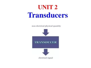
UNIT 2
UNIT 2. Transducers. Transducer. Devices used to transform one kind of energy to another . Advantages of electrical transducers Easy amplification, small power requirements, easy data transmission & recording Disadvantages Low reliability and high cost Requirement of a transducer

UNIT 2
E N D
Presentation Transcript
UNIT 2 Transducers
Transducer • Devices used to transform one kind of energy to another. • Advantages of electrical transducers Easy amplification, small power requirements, easy data transmission & recording • Disadvantages Low reliability and high cost • Requirement of a transducer Linearity , Reproducibility , High reliability & sensitivity, Good dynamic response, high SNR, No hysteresis & ruggedness
TRANSDUCER • ACTIVE Self generating transducers or transducers which develop their output in the form of voltage or current without any auxiliary source.eg: thermocouple, piezo electric transducers • PASSIVE Transducers in which electrical parameters R, L ,C changes with changes in input signal. It requires power supply for its operation .eg: resistive, capacitive, inductive trasducer JOBY JOHN
TRANDUCER • ANALOG Transducer which converts input signal into an analog output . Mainly divided into Electromechanical , opto electric Type Eg: thermistor, LVDT, stain guages • DIGITAL Transducer which converts input signal into discrete output /pulses . 2 types a) Frequency generating b) Digital encoders Eg: digital encoders, optical encoders, electromagnetic transducers
Electro Mechanical Transducers Input(Physical Variable) is converted to Mechanical Displacement Or Strain, using Primary Sensors. Then , it is converted to Electrical Output with the help of electromechanical Transducers.
Electro Mechanical Transducer Potentiometric Transducers • Based on the linear dependence between total impedance and conductor length. • Several technologies: wire bound, conductive plastic, mixed,… • Both for linear and angular displacement measurements • R(l) = (l/L) R0 • Angular and rotary Sensor, Linear Translation Sensor
Electro Mechanical Transducer • Potentiometers Translational Type (passive) Rotational Type • Can be used to measure position, displacement & level • Advantages: Suitable for large amplitude of displacement ,Electrical efficiency is high, inexpensive • Disadvantages: Large force is required to move sliding contacts and it also produce noise
Electro Mechanical Transducer Inductive Transducers ( mainly for displacement) • Two Types : Self Generating Type (Electrical Generator Principle) Or Passive Type ( Change in Inductance) • Active: Motion of conductor in a magnetic field produces a voltage in the conductor • Passive :Variation in Self Inductance and Variation in Mutual Inductance Implemented by 1.Number of lines 2. Geometric Configuration 3.Permeability of magnetic Material • L= e/(di/dt) = N2/R= N2µA/l
a) Number of Turns • Angular Inductive input output • Linear Inductive • As N Changes , L and output Changes
b) Change in Permeability • Iron core is surrounded by the winding. When the iron core is inside the winding ,its permeability is increased ,hence the inductance. When the iron core is moved out of the winding, permeability decreases, resulting in reduction in self inductance of the coil
c)Variable Reluctance Type Transducer • Coil is wound on a ferromagnetic core. Displacement to be measured is applied to ferromagnetic target ( No Physical contact with core, but separated by an air gap ). • Reluctance of the magnetic path is determined by the Size of the air Gap. • Self Inductance of the coil L=N2/Ri+Rg, where N - Number of turns Ri - Reluctance of iron parts Rg - Reluctance of air gap
c)Variable Reluctance Type Transducer L= N2/Rg , since Ri is negligible Rg = lg/µ0* Ag where lg – length of air gap, µ0 – Permeability, Ag – Area of the flux path through air . Here µ0 and Ag are constants. Rg is proportional to lg When the target is near the core, length is small and hence self inductance is large , but when the target is away from the core, reluctance is large ,resulting in smaller value of inductance
Linear Variable Differential Transducers • Passive Inductive transducer widely used for translating a linear motion into an electrical signal Operation: • When core is in its null position , equal voltages are induced in the two secondary windings Es1 = Es2 . Hence E0 = 0.(ie,E = Es1- Es2 ). • If the core is moved to the left of the null position, E0= Es1- Es2, in phase with Es1. (ie,E0 =+ve, ø = 00 ) • If the core is moved to the right of the null position, E0=Es2-Es1, in phase with Es2 ( ie,E0 = -ve, ø =1800 )
Linear Variable Differential Transducers • Construction: Single primary winding P1(connected to AC Source) and two secondary winding S1 & S2 (equal No. of turns and identically placed on either sides of the primary winding) wound on a hollow cylindrical former. A movable soft iron ( Nickel –Iron alloy, movement is attached to it) core slides within the former and affect the magnetic coupling between primary and two secondaries.
Various Core Positions and variation of output voltage & phase with displacement Linear Variable Differential Transducers
Disadvantages Linear Variable Differential Transducers Advantages • Higher output volt for small changes in core position(50-300mv/mm) • Output voltage is linear upto 5mm displacement • Infinite resolution & High sensitivity • Low Power consumption (less than 1 W) and low Hysteresis • Less friction • Sensitive to stray magnetic field. • Temperature affect transducer operation. • Demodulator network must be used if a dc output is required
Capacitive transducers • Changes in position is converted to changes in the capacitance • Capacitance C = KA/d K- dielectric constant A- Area of the capacitor Plates D- distance between the plates • Capacitance increases if 1.Effective area of the plate is increased 2.If the material has high K value 3.If the distance between the plates is reduced A)Variable Distance Type (pressure - microphone) • Here diaphragm is deflected with respect to the applied pressure leads to change in distance between the plates, hence the capacitance
Capacitive transducers b) Variable Area Type • Here one plate is kept fixed called stator, and the movable plate is called rotor, to which movement is connected. • Change in position of the rotor with respect to the stator causes change effective area , hence capacitance
Capacitive transducers C)Differential Capacitive Transducer • A movable plate is kept in midway between the two fixed plates. Then C1= C2, and E1=E2 = E/2 Differential output = 0. • Let the movable plate displaced x in the upward direction, then C1= KA/(d-x) & C2=KA/(d+x) Then E1= C2E/(C1+C2) =(d-x)E/2dand E2= C1E/(C1+C2) =(d+x)E/2d Differential output = ± xE/d.
Capacitive transducers D)Variable Dielectric Type Initially C= Kwl1/d+ KKrwl2/d Let the Dielectric is moved through a distance x, then change in capacitance ∆C= Kw x(Kr-1)/d Uses of Capacitive Transducers Can be used for the measurement of presure, force, Humidity etc Advantages • Good Frequency Response • High Input Impedance • Highly sensitive & Operational with small force • Good resolution Disadvantages • Nonlinear behaviour due to edge effect • Temperature variation ,dust particle in moisture affect the performance
Resistive Traducers Resistance Temperature Detector(RTDs) Based on the temperature dependence of resistivity of all metals and alloys. Although virtually all metals can be employed, platinum is used almost exclusively: predictable response, long-term stability and durability ,ultimate in accuracy . Other RTDs are Nickel, Copper etc All RTD’s have positive temperature coefficients Advantages Linearity over wide Temperature Range Better Stability at higher temperatures Disadvantages Low sensitivity & high cost Can be affected by contact resistance, shock, acceleration
RESISTIVE TRANDUCERS • Rt- Resistance of a conductor at temperature t0C • R0- Resistance of a conductor at temperature 00C • à- Temperature coefficient of resistance • Then • Rt= R0(1+à∆t)
RESISTIVE TRANDUCERS • Thermistor • Thermo resistive sensors but fabricated with metal-oxide materials that behave like semiconductors • They usually present a Negative temperature coefficient (NTC), although PTC (Positive temperature coefficient) ,thermistors are also available. • Low-accuracy and low stability sensors, but low cost, they present an exponential-like dependence on temperature. • Thermistors are available in the form of beads, disc,washer and rod • Merits: Fast response, Good sensitivity in NTC region , Small size ,low Cost. • Demerits: Non-linear behaviour, unsuitable for wide range, Self heating
Resistance versus Temp . Graph RESISTIVE TRANDUCERS Thermistor • R ref - Resistance of a thermistor at temperature T ref. • R- Resistance of a thermistor at temperature T • ß- Temperature coefficient of resistance Then
RESISTIVE TRANDUCERS Strain guages ( variable resistance transducers) Passive transducer which is used to measure strain produced by a Force by the changes in electrical resistance in wires. Piezoresistive effect : The impedance( due to the change in length or diameter) of a metal wire changes when the material is mechanically deformed. This is the origin for a widely used sensors known as strain gauges. When a stress is applied on wire , its length increases and diameter decreases . i.e , R = ÞL/A In these sensors, the unitary change in resistance is proportional to the elongation (strain) through a parameter known as gauge factor (K). ∆R/R = K (∆L/L). Measurement of sensitivity of a material to strain is called guage factor.
STRAIN GUAGES Different Types Strain Guages Wire Strain Guage Foil Stain Guage Semiconductor Strain guage Resistance Wire Gauges have 2 Basic forms: Unbonded & Bonded 1.UNBONDED It is connected in a bridge circuit With no load applied bridge is balanced. When load is applied, resistance change occurs resulting an output voltage in the bridge In unbonded Resistance strain guages, Wire streched Between two points in an Insulating Medium(D= 25µm) ,
STRAIN GUAGES 2)BONDED A wire is looped back and forth on a mounting plate (carrier) which is usually cemented to a member undergoing stress R = ÞL/A Different Types of Wire Strain guages Grid Type Rosette Type Torque Type Helical type
STRAIN GUAGES Grid Helical Torque Rosette
STRAIN GUAGES Grid Type Measuring axis of a strain gauge is along the longitudinal axis, but in most applications , some degree of strain is present along the transverse axis of the gauge .i.e, transverse sensitivity can not be completely eliminated ,in high accuracy measurements. So compensation is required… Rosette type Compensation for transverse sensitivity is to place several gauges on members surface with a known angles between them(450) Characteristics of strain guages for better measurement 1.High value of K 2.R should be as high as possible 3.Low resistance temperature coefficient 4. No hysteresis
STRAIN GUAGES Foil Strain Guage Strain is measured with the help of a metal foil . Ex: Nickel, Platinum Nichrome, Constantan(Ni+cu), Isoelastic (Ni+Cr+Mo) Advantages Greater dissipation capability due to large surface area. Hence in can be operated in higher Temperature range Better bonding & fabricated in any shape and etched on the carrier. Longitudinal sensitivity is 5% more than wire type with equal K value Transverse sensitivity & hysteresis is smaller to ½ to 1/3 of wire Type Resistance in between 50-1000 ohms & thickness of the film is about 0.2mm
STRAIN GUAGES Semiconductor strain gauges Here change in resistance due to resistivity change rather than dimensional change in metallic gauge eg: Ge, Si Advantages High value of Gauge Factor (50 times more than wire type) indicates higher change in resistance and hence good accuracy Hysteresis characteristics of Semiconductor strain gauges are excellent Better frequency response & small in size Disadvantages Sensitive to temperature changes Linearity is poor Expensive
Piezo Electric Transducer Active tranducer used for the measurement of force or strain Piezo electric effect: Crystalline materials such as Quartz, barium titanate , produces an emf when they are placed under stress.(reversible) Structure: Here crystal is placed between a solid base and a force summing member. Force entering the transducer through its pressure port applies pressure vat the top of the crystal. This produces an emf across the crystal proportional to the magnitude of applied pressure
Piezo Electric Transducer Basic expression for output voltage E =Q/Cp, where Q – generated Charge, Cp - shunt capacitance. Let K- Coupling Coefficient K= Mech.E converted to Ele. E/Applied Mech. E K= Ele.E converted to Mech. E/Applied Ele. E Properties of Piezo electric crystal Stability High Output Very good Frequency Response Sensitive to temperature and humidity Applications Measurement of force, High frequency accelerometer, as mass to frequency converter, Measurement of temperature
Load cell (Pressure cell) Used to measure Heavy loads using strain guages As the stress/load is applied along Z direction, steel bar experience a compression along this direction, and an expansion along X & Y axis. As a result , gauge A experience a decrease in resistance while the other B undergoes increase in resistance. When these two gauges and gauges on the other sides of the steel are connected to form a bridge circuit, sensitivity is multiplied by four times. So it load cell is sensitive to small values of stress as well as heavy loads
Thermo Couple Active transducer used for measurement of temperature Principle: When a pair of wires made of disimilar metals is joined together at one end, a temperature difference between the two ends of wires produces a voltage between the two wires (Seebeck effect) • The magnitude of this voltage depends on the material used for the wire and temperature difference between the joined ends and other ends • Temperature difference between the sensing junction and other ends is a critical factor, the latter are kept at constant reference temperature
Thermo Couple A series of thermocouple connected together is called a thermopile Thermocouple is made of different alloys covering a range of -2700 C to 27000 C J- Iron Constantan, T-Copper Constantan E- Chromel-Constantan, K- Chromel-Alumel, S- Platinum-Rhodium etc
Limitations Thermo Couple Advantages • Rugged Construction • Wide range (-2700 C to 27000 C) • Good Accuracy • No need of bridge circuit • Good reproducibility • Cheap • Cold junction & other compensation are required for accurate measurement • Nonlinear behavior • Signal amplification is required
Ultrasonic Transducers Ultrasonic sensors generate high frequency sound waves(above 20khz) and evaluate the echo which is received back by the sensor. Sensors calculate the time interval between sending the signal and receiving the echo based on the the ultrasound frequency, and the sound velocity of the propagation medium etc to determine the distance. Piezo electric transducers can be used as transmitters and receivers When an alternating current is applied Piezo electric transducers, causes them to oscillate at very high frequencies, thus producing very high frequency sound waves. Also piezoelectric crystals generate a voltage when force is applied to them, So the same crystal can be used as an ultrasonic detector
Ultrasonic Transducers It can be used to detect level of a fluid in a tank, speed of an object through air or water etc
Ionization Transducer Most widely used for low-pressure measurement Operation: A regulated electron current (typically 10 mA) is emitted from a heated filament. Electrons emitted from the filament move several times in back and forth movements around the grid before finally entering the grid (+150 volts). During these movements, some electrons collide with a gaseous molecule to form a pair of an ion and an electron (Electron Ionization) and these ions pour into the collector (-30 volts) to form an ion current. Since the gaseous molecule density is proportional to the pressure, the pressure is estimated by measuring the ion current .The number of these ions is proportional to the gaseous molecule density multiplied by the electron current emitted from the filament . This current is amplified and displayed by a high-gain-differential amplifier .
Ionization Transducer This ion current will differ for different gases at the same pressure; that is, a hot filament ionization gauge is composition-dependent
ProximityTransducers Detect the presence of nearby objects without any physical contact Operation : A proximity sensor often emits an electromagnetic field or electromagnetic radiation and observes changes in the field or return signal. An Inductive proximity sensor always requires a metal target.
Proximity Transducers Target Signal Switching evaluator Amplifier Advantages: Due their non-contact mode of operation ,direct contact with the object is avoided (No moving parts or contacts, hence functions without wear). High degree of protection against vibration and shock, stress as well as dirt, dust and humidity ( can also be used in extreme conditions)
ProximityTransducers Operation
Proximity Transducers OPERATION : An inductive proximity sensor comprises an LC oscillating circuit, a signal evaluator/trigger circuit and a switching amplifier/output circuit . The coil of this oscillating circuit generates a high-frequency alternating electromagnetic field. This field is emitted at the sensing face of the sensor. If attenuating material/ Target nears the sensing face, eddy currents are generated in the case of non ferrite metals . In the case of ferro magnetic metals, hysteresis and eddy current loss also occurs. These losses draw energy from the oscillating circuit and reduce oscillation. The signal evaluator detects this reduction and converts it into a switching signal.
Hall Effect sensors Hall Effect :When a current carrying conductor is subjected to magnetic field, a voltage is developed across the conductor transverse to the current flow and perpendicular to the magnetic field. The Hall coefficient is defined as the ratio of the induced electric field to the product of the current density and the applied magnetic field No magnetic field - Straight line current flow With Perpendicular Mag. Field – Curved path and accumulate on the surfaces ,produces an emf For a simple metal strip( charge carriers: Electrons only) the Hall voltage VH= -IB/net I= current, B= Mag.Flux t= thickness, n= charge carrier density
Hall Effect sensors A Hall effect sensor : Analog/Digital transducer that varies its output voltage in response to a magnetic field ( With a known magnetic field, its distance from the Hall plate can be determined). Hall sensor can be used to measure the current without interrupting the circuit. Hall effect sensors are used for proximity switching, displacement, positioning, speed detection, and current sensing applications Digital Type: Two magnets are placed on the disc .As the disc rotates ,LED tuns ON/OFF depends on the position of the coil & magnet
Photoconductive cell Passive transducer used for the measurement of radiation intensity. Electrical resistance to the current flow varies as the light intensity striking in it. When the photocell has appropriate light is incident upon it, its resistance is low and the current flow through the relay is high to operate the relay. When the light is interrupted shut off partially or completely, resistance of the photocell increases ,thereby reducing the current through the relay.
Photoconductive cell Photo resistors/LDR are basically photocells (CdS, PbS, InSb) A photo resistor is made of a high resistance semiconductor . If light falling on the device is of high enough frequency, photons absorbed by the semiconductor give bound electrons enough energy to jump into the conduction band. The resulting free electron conduct electricity, thereby lowering resistance