Download
1 / 23
240 likes | 265 Vues
Learn how to select and utilize power supplies and dc/dc converters effectively for your applications. Understand various types and technologies, circuit selection, design considerations, thermal issues, specifications, performance metrics, and protection features.

E N D
How to Select and Use Power Supplies and dc/dc Converters for Your Applications Fang Z. Peng Dept. of Electrical and Computer Engineering Michigan State University Phone: 517-355-1608, Fax: 517-353-1980 Email: fzpeng@egr.msu.edu Presenter: Deepak Gunasekaran, PhD Candidate, PE Lab, MSU
Contents • Introduction to Power Supplies and dc/dc Converters • Types & Technologies of Power Supplies and dc/dc Converters • Circuit Selection and Design • Thermal Requirements and Design Issues
Introduction to Power Supplies and dc/dc Converters • Available/Raw Power Sources • AC or DC (frequency) • Un-regulated (changes with load, prime source, etc.) • Voltage (different level, polarity, isolation) • Non-protected (against over load, fault, temp., etc.) • Load Demand • Different AC or DC (frequency) • Regulated (against load, prime source, etc.) • Voltage (different level, polarity, isolation) • Protected (against over load, fault, temp., etc.)
Specs, Performance and Protection • Voltage ripple (+-50 mV, or 5%) • Isolation (e.g., 1,500 V ac for 1 min.) • Load regulation (e.g., 3%) • Dynamic response (transients, wake-up time, etc.) • Short circuit protection • OC protection • OV protection • OT protection
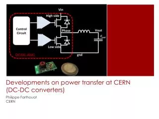
Introduction to Power Supplies and dc/dc Converters –cont. Power Supply Desired power out (V, I, P, F) Power & Electronic Circuits Raw power in To loads: Electronic ckts Motor Computer Equipment Battery Fuel Cell AC Outlet Solar Control
Power Supplies and dc/dc Converters –Types & Technologies • AC-DC Power Supply (or AC Adapter) • Change ac power into regulated dc power, e.g., a typical AC Adapter takes 120 V ac input and converts it to regulated 5 Vdc. • Dc/dc Converters • Change dc at one voltage potential to a dc at a different voltage potential • DC-AC Power Supply (for example, UPS, 12Vdc-120Vac adapter) • AC-AC Power Supply/Regulator (for example, line regulator)
AC-DC Power Supplies-Circuit Selection and Design • Using Linear Regulators • Using LDO Regulator http://www.national.com/pf/LM/LM78M05.html Step-down Xfmer 120 V AC Regulator • For low power (several watts or below) applications. • Low efficiency, large size and weight (bulky step-down line transformer) • Low cost
Charge Pump • Inductor-less Boost, Buck • Stray inductance enough to limit current • TI, Linear Technology have several ICs
AC-DC Power Supplies-Circuit Selection and Design • Using Switching-Mode • High efficiency • Small size and light weight • For high power (density) applications TI Power Supply Technologies Poster http://www.electronicproducts.com/ http://www.linear.com/index.jsp http://www.linear.com/3770
Selecting the Right dc/dc Converter –cont. VBAT = 3.7 V nom, BIN_BB = 1.2 V Load Current = 600 mA Power delivered to load = 600 mA * 1.2 V = 720 mW Power converted to heat = 600 mA * (3.7-1.2) = 1,500 mW Total power consumed = 720 mW + 1,500 mW = 2,200 mW 32% goes to work, 68% goes to heating user hand and ear when using a Linear Regulator for a mobile device • Linear regulators: • Inexpensive • small footprint • low part count • low noise • high ripple rejection • Switching regulators: • a bigger footprint • higher part count, • more cost • prone to conducted and radiated EMI. VBAT = 3.7 V nom; BIN_BB = 1.2 V Load Current = 600 mA Converter efficiency = 90% Power delivered to load = 600 mA * 1.2 V = 720 mW Total power consumed=720 mW * (1/0.9)=800 mW Power converted to heat= 800 mW - 720 mW = 80 mW 90% goes to work, 10% goes to heating user hand and ear When using a Switch-mode regulator for a mobile device.
Selecting the Right dc/dc Converter • The Need for dc/dc Converters • E.g., a single AA alkaline battery produces 1.5 V when fully charged and its voltage drops to as low as 0.9 V when becoming depleted. • Dc/dc Converter Types • Buck • Boost • Buck-Boost • Dc/dc Converter Technologies • Linear Regulators • Switching Regulators • Charge Pumps The MCP1703 LDO is one type of dc/dc linear regulator
Power Losses and Thermal Design • For example, a 7815 linear regulator with input voltage of 20 V and output current of 1 A. The power loss is (20-15)Vx(1 A)=5 W. • From the chip to the ambient, DTi can be calculated according to the thermal circuit using Ohm’s law (R=V/I), where R is the thermal resistance, V is the temperature and I is the power dissipation. Where: Tcase is case Temp. Tambient is ambient Temp. Pdissipation is power loss Pin is input power Pout is output power hop is efficiency under given operating conditions
Power Losses and Thermal Design--A more detailed thermal circuit • W : Device power loss • Tj : Junction temperature of device • Tc : Device case temperature • Tf : Temperature of heatsink • Ta : Ambient temperature • Rth(j-c) : Thermal resistance between junction and case, specified in datasheet • Rth(c-f) : Contact thermal resistance between case and heatsink, specified in datasheet • Rth(f-a) : Thermal resistance between heatsink and ambient air, specified by the heatsink manufacturer
Power Losses and Thermal Design Tj=W×{Rth(j-c) + Rth(c-f) + Rth(f-a)} +Ta Rth(f-a) =1/W (Tj – Ta) - Rth(j-c) - Rth(c-f)
Example • Device : 7815 (Linear regulator) • Vin=20V, Vo=15V, Io=1A • W : (20-15)×1=5 watts • Rth(j-c) : 5 °C/W • Rth(c-f) : 0.5 °C/W, Greased surface • Tj <= 125 °C • Ta=25 °C An assortment of 78XX series Rth(f-a) =1/W (Tj – Ta) - Rth(j-c) - Rth(c-f) • Rth(f-a) :14.5 °C/W An assortment of heatsinks
Some Tips • Fully understand your requirement. Make a spec sheet • Carefully read datasheets and application notes • Get multiple samples from vendors to try different circuits. • Several ICs available for low and medium power apps. • Simultaneously work on thermal design and chassis design (multi-task !) • (Try R-tools by Mersen . Good software tool for designing heat sinks) • Pay attention to EMI issues during layout. Use shielded inductors, Low ESL capacitors, common mode and DM chokes, etc.