PCB Layout Planning and Design
PCB Layout Planning and Design. BLOCK DIAGRAM.

PCB Layout Planning and Design
E N D
Presentation Transcript
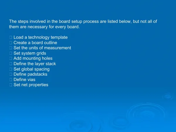
BLOCK DIAGRAM • All electronic equipments can be considered as systems comprising a set of interacting elements responding to inputs to produce outputs. It is quite possible that a system may be too complex to be analyzed in detail. It is therefore, necessary to divide it into sub-systems and then integrate them.
BLOCK DIAGRAM (Cont…) • Each sub-system would then represent a functional block, and the combination of all the blocks would constitute the functional ‘Block Diagram’ of the equipment. • A block is only a ‘black box’ with certain inputs and outputs, but performing a definite function.
BLOCK DIAGRAM (Cont…) • The lines interconnecting these blocks indicate the signal flow from block to block or circuit to circuit. Understanding of the circuit function becomes easy with a block diagram.
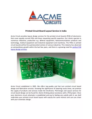
SCHEMATIC DIAGRAM • A schematic diagram is a graphical representation of interconnections of various electronic, electrical and electromechanical components of an equipment. The schematic is the first step in an electronic circuit design because it displays and identifies the components that make up the equipment.
SCHEMATIC DIAGRAM (cont..) • Further, the first step in designing a printed circuit is to convert the schematic diagram in to an art master. • Therefore, for any printed circuit designer, it is important to learn to read and interpret the schematic diagram. • However, the schematic diagram does not show any of the mechanical details of the printed circuit board.
Uses Of Schematic Diagram • It gives visibility into the status of all parts of the design process; • Schematics are the primary source for developing deliverables to product design and manufacturing groups; • Design variants are built around slightly differing schematics; • Test departments rely on schematics; • Field service relies on schematics; and • Bills-of-materials are generated from schematics.