So far
So far. We have introduced the Z transform T he digital equivalent of the Laplace transform It facilitates the solving of difference equations It allows to easily evaluate the system’s response It is critical in designing linear filters The Discrete-time Fourier Transform (DTFT)

So far
E N D
Presentation Transcript
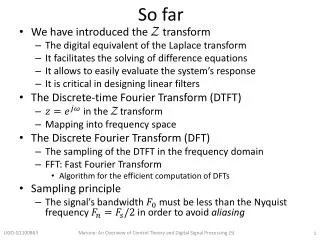
So far • We have introduced the Z transform • The digital equivalent of the Laplace transform • It facilitates the solving of difference equations • It allows to easily evaluate the system’s response • It is critical in designing linear filters • The Discrete-time Fourier Transform (DTFT) • in the transform • Mapping into frequency space • The Discrete Fourier Transform (DFT) • The sampling of the DTFT in the frequency domain • FFT: Fast Fourier Transform • Algorithm for the efficient computation of DFTs • Sampling principle • The signal’s bandwidth must be less than the Nyquist frequency in order to avoid aliasing Matone: An Overview of Control Theory and Digital Signal Processing (5)
Digital Signal Processing 3 Digital Filters • An LTI system to frequency select or discriminate • Two classes • Finite-duration impulse response (FIR) Filters • Infinite-duration impulse response (IIR) Filters Matone: An Overview of Control Theory and Digital Signal Processing (5)
FIR filter • The filter’s unit impulse response is of finite duration • Its response settles to zero in a finite time • There is no “feedback” • Difference equation • Also referred to as recursive or moving average filters. Matone: An Overview of Control Theory and Digital Signal Processing (5)
IIR filter • The filter’s unit impulse response is of infinite duration • Difference equation • Output is recursively computed from previous computed values → infinite duration response Matone: An Overview of Control Theory and Digital Signal Processing (5)
FIR filter example: Moving Average (MA) In general For Matone: An Overview of Control Theory and Digital Signal Processing (5)
To the Z domain Recall: when an LTI system is represented by the difference equation Then Matone: An Overview of Control Theory and Digital Signal Processing (5)
System function Coefficients a and b are With a pole at the origin, and a zero at -1. Matone: An Overview of Control Theory and Digital Signal Processing (5)
MA_example.m >> a=1; b=[1/2 1/2]; >> zplane(b,a) Matone: An Overview of Control Theory and Digital Signal Processing (5)
Recall: difference equation and the filter command • In general, a difference equation is of the form • The MATLAB filter command solves the difference equations numerically • Given the input sequence , the output sequence is computed using >> y = filter(b, a, x) Matone: An Overview of Control Theory and Digital Signal Processing (5)
Let’s apply the filter to a data stream • Step function imbedded in noise is shown to the right. • Let’s apply the N=2 moving average filter >> a=1; >> b=[1/2 1/2]; >> y = filter(b, a, x); MA_example.m Matone: An Overview of Control Theory and Digital Signal Processing (5)
MA_example.m Matone: An Overview of Control Theory and Digital Signal Processing (5)
The impulse response function MA_example.m >> h = filter(b, a, delta) Matone: An Overview of Control Theory and Digital Signal Processing (5)
The impulse response function From the filter command The system’s response Matone: An Overview of Control Theory and Digital Signal Processing (5)
Comparing the filter output with convolution MA_example.m >> y = conv(x,h,’same’) Matone: An Overview of Control Theory and Digital Signal Processing (5)
Increasing filter order MA_exampleB.m Matone: An Overview of Control Theory and Digital Signal Processing (5)
Increasing filter order MA_exampleB.m Matone: An Overview of Control Theory and Digital Signal Processing (5)
Increasing filter order MA_exampleB.m Matone: An Overview of Control Theory and Digital Signal Processing (5)
Frequency response of moving average filter MA_exampleB.m >> [H, f]= freqz(b,a,1000,Fs) Matone: An Overview of Control Theory and Digital Signal Processing (5)
Suppression but with phase delay MA_exampleC.m Matone: An Overview of Control Theory and Digital Signal Processing (5)
Analog-to-digital filter transformation • First, we design an analog filter that satisfies the specifications. • Then we transform it into the digital domain. Many transformations are available • Impulse invariance • Designed to preserve the shape of the impulse response from analog to digital • Finite difference approximation • Specifically designed to convert a differential equation representation to a difference equation representation • Step invariance • Designed to preserve the shape of the step response Bilinear transformation • Most popular technique • Preserves the system’s function representation from analog to digital Matone: An Overview of Control Theory and Digital Signal Processing (5)
Filter stability in the analog and digital domain Digital domain (z-plane) Analog domain (s-plane) Region of stability Poles must have a negative real part Poles are inside the unit circle 21 Matone: An Overview of Control Theory and Digital Signal Processing (5)
Bilinear transformation Digital domain (z-plane) Analog domain (s-plane) Mapping between the two stability regions 22 Matone: An Overview of Control Theory and Digital Signal Processing (5)
Bilinear transformation Digital domain (z-plane) Analog domain (s-plane) Sampling time 23 Matone: An Overview of Control Theory and Digital Signal Processing (5)
Transformation example Transform into a digital filter with sampling . Sol. Matone: An Overview of Control Theory and Digital Signal Processing (5)
Transformation example bilinearexample.m Matone: An Overview of Control Theory and Digital Signal Processing (5)
Transformation example bilinearexample3.m Matone: An Overview of Control Theory and Digital Signal Processing (5)
Filter Design • Filter specifications • Constraints on the suppression factor • Constraints on the phase response • Constraints on the impulse response • Constraints on the step response • FIR or IIR • Filter order • Typical filters • Low pass, High pass, Band pass and Band stop Matone: An Overview of Control Theory and Digital Signal Processing (5)
FIR or IIR? • Advantages of FIR filters over IIR • Can be designed to have a “linear phase”. This would “delay” the input signal but would not distort it • Simple to implement • Always stable • Disadvantages • IIR filters are better in approximating analog systems • For a given magnitude response specification, IIR filters often require much less computation than an equivalent FIR Matone: An Overview of Control Theory and Digital Signal Processing (5)
Low pass (LP) filter specifications • LP filter • low frequencies pass, high frequencies are attenuated. • Include • target magnitude response • phase response, and • the allowable deviation for each • Transition band • frequency range from the passband edge frequency to the stopband edge frequency • Ripples • The filter passband and stopband can contain oscillations, referred to as ripples. Peak-to-peak value, usually expressed in dB. Matone: An Overview of Control Theory and Digital Signal Processing (5)
High pass (HP) filter specifications • HP filter • High frequencies pass, low frequencies are attenuated. Matone: An Overview of Control Theory and Digital Signal Processing (5)
Band pass (BP) filter specifications • BP filter • a certain band of frequencies pass while lower and higher frequencies are attenuated. Matone: An Overview of Control Theory and Digital Signal Processing (5)
Band stop (BS) filter specifications • BS filter • attenuates a certain band of frequencies and passes all frequencies not within the band. Matone: An Overview of Control Theory and Digital Signal Processing (5)
A few types of IIR filters • Butterworth • Designed to have as flat a frequency response as possible in the passband • Chebyshev Type 1 • Steeper roll-off but more pass band ripple • Chebyshev Type 2 • Steeper roll-off but more stop band ripple • Elliptic • Fastest transition Matone: An Overview of Control Theory and Digital Signal Processing (5)
Comparison Sampling frequency set to 16384 Hz Filter order set to 10, cutoff set at 1 kHz Difficult comparison: specifications for each filter can be very different filter_plots.m Matone: An Overview of Control Theory and Digital Signal Processing (5)
Comments • Chebyshevfilter has a steeper roll-off with respect to the Butterworth filter • The elliptical filter has the fastest roll-off • Elliptical’sattenuation factor at high frequency is constant, unlike the others. • Elliptical has the least phase delay with respect to the others • Notice: the performance of a FIR window filter of 10th order is also shown. For it to achieve the same performance as the others, the filter order must be increased significantly filter_plots.m Matone: An Overview of Control Theory and Digital Signal Processing (5)
Comments • The Butterworth filter has a flattest response when compared to the others. • There is a trade off • The faster the roll-offs, the greater the ripples filter_plots.m Matone: An Overview of Control Theory and Digital Signal Processing (5)
MATLAB’s fdatool • Filter Design and Analysis Tool • Allows you to design (visually) a digital filter • Can export the filter into different formats • Filter coefficients • MATLAB’s transfer function object • … >> fdatool Matone: An Overview of Control Theory and Digital Signal Processing (5)
MATLAB’s fdatool Exporting • Coefficients a, b • Transfer function object Hd • Second-order-sections sos The system function H(z) can be factored into second-order-sections. The system is then represented as a product of these sections. Assuming input signal x, the output y: y = filter(Hd,x) y = filter(b,a,x) y = sosfilt(sos,x) Matone: An Overview of Control Theory and Digital Signal Processing (5)
Sampling: Analog-to-Digital conversion • Transforms analog signal to digital sequence • Main components of an A/D converter Encoder c C/D Quantizer Bit stream : corresponds to discrete time sequence Analog signal : real valued function of a continuous variable Matone: An Overview of Control Theory and Digital Signal Processing (5)
Sampling: Analog-to-Digital conversion • Transforms analog signal to digital sequence • Main components of an A/D converter Encoder c C/D Quantizer Quantization interval : amplitude is integer multiple of (determined by the number of bits) Quantizer: maps continuous range of possible amplitudes into a discrete set of amplitudes Sampler C/D: continuous-to-discrete converter or an ideal A/D converter: Matone: An Overview of Control Theory and Digital Signal Processing (5)
Sampling: Analog-to-Digital conversion • Transforms analog signal to digital sequence • Main components of an A/D converter Encoder c C/D Quantizer Encoder: produces a sequence of binary codewords Matone: An Overview of Control Theory and Digital Signal Processing (5)
Sampling: Analog-to-Digital conversion • Anti-aliasing filter • Signals in physical systems will never be exactly bandlimited, aliasing can occur • (Analog) lowpass at the Nyquist frequency. • This minimizes signal energy above the Nyquist frequency, minimizing aliasing C/D AA Matone: An Overview of Control Theory and Digital Signal Processing (5)
Sampling: Analog-to-Digital conversion • Anti-aliasing filter • Signals in physical systems will never be exactly bandlimited, aliasing can occur • Analog lowpass filter that minimizes signal energy above the Nyquist frequency C/D AA Matone: An Overview of Control Theory and Digital Signal Processing (5)
And back: Digital-to-Analog conversion Two steps involved • Conversion to rectangular pulses • Pulses cause multiple harmonics above the Nyquistfrequency • This excess noise is reduced with an (analog) low pass filter (or reconstruction filter) LP filter Convert to impulses Matone: An Overview of Control Theory and Digital Signal Processing (5)
Thank You!! Matone: An Overview of Control Theory and Digital Signal Processing (5)