Electronics Technology for IC
Electronics Technology for IC.

Electronics Technology for IC
E N D
Presentation Transcript
Section 1: Learning Objectives.- Identify the different properties between Conductors, Insulators, and Semiconductors. - Translate the basics of time, weight, distance and electrical units.- How to simplify, and round large numbers, recognize and use Scientific notation while using its proper name and symbol. - Be aware of the differences in a digital and analog multi-meter.
History of the discovery of Electricity • In popular literature Benjamin Franklin is often credited with the discovery of electricity. • However, it was known at least as early as 600 BC that amber (fossilized sap) would attract dust and other small particles after being rubbed with wool. • This property was called electricity after the Greek word for amber, elektron.
How Electricity flows in: • Conductors Elements that have fewer than four valence electrons are called metals. With fewer than four valence electrons it is relatively easy for atoms to exchange electrons. Copper, for example, has only one electron in its valence shell. • Insulators Elements with more than four valence electrons are called non-metals. The electrons in non-metals form tight bonds with electrons of nearby atoms, locking them in place in the mass of material. Therefore, non-metals are generally non-conductors. Actually, most non-metals are not well suited for use in electrical circuits since they are either liquid or gaseous at normal temperatures and pressures. Because of this, most insulators are made of compounds such as glass, ceramic or plastic. • Semiconductors Elements that have four valence electrons, the halfway point between conductors and insulators, are called semiconductors. They are basically insulators but can be doped with impurities that cause them to act as conductors.
Semiconductors Silicon Germanium
Direction of Electrical Flow • Electron Flow • Electron flow considers the actual flow of negatively charged electrons-from negative to positive-as current flow. It is more difficult to visualize than conventional flow because the current seems to flow from a low pressure (negative) to a high pressure (positive). In schematic diagrams the current flows against the arrows in semiconductor devices. • Conventional Flow • Conventional flow considers flow of an imaginary (positively-charged) fluid from positive to negative. It is easier to visualize than electron flow because the current flows from a high pressure (positive) to a low pressure (negative). In schematic diagrams the current flows in the direction of arrows in semiconductor devices
The Elements of Electricity • Voltage • Current • Resistance • Types of Current: AC and DC • Circuits • Closed • Open • Short
VOLTAGE • Because like charges repel and unlike charges attract, electrons will move from the negative source to the positive end. • The applied force that causes the electrons to flow is called voltage (after the scientist Alessandro Volta) or electromotive force (emf). • We give it the symbol or ℰ in equations. Voltage is measured with a voltmeter or multimeter and is the potential difference between two points in a circuit. The basic unit is the volt (V).
CURRENT • Current is a flow of electrical charge carriers, usually electrons or electron-deficient atoms. • The common symbol for current is the uppercase letter I. The standard unit is the ampere, symbolized by A.
RESISTANCE • Opposition of a circuit to the flow of electric current. Resistance is measured in Ohms. • Resistance is represented by the Greek symbol- Omega Ώ.
Forms of Current • There are 2 types of current • The form is determined by the directions the current flows through a conductor • Direct Current (DC) • Flows in only one direction from negative toward positive pole of source • Alternating Current (AC) • Flows back and forth because the poles of the source alternate between positive and negative
The Water Analogy • Resistance is a property that slows the flow of electrons. • Using the water analogy, Resistance is anything that would slow the flow of water through a pipe
Measuring Electricity • The scientific world uses the International System of Units (SI units) to measure things. The International System of Units starts with three basic units: • The kilogram, the meter and the second. Every other unit is derived from these three basic units. • For example: • To know what a volt is, we have to know what a watt is. • To know what a watt is, we have to know what a joule is. • To know what a joule is we have to know what a meter and a Newton are. • Finally, to know what a Newton is we have to know what a kilogram a meter and a second are.
Base Units • Kilogram (kg) - The kilogram is the unit of mass that is equal to the mass of the international prototype of the kilogram. • The kilogram is a particular cylinder of platinum-iridium alloy that is preserved in a vault at Sevres, France, by the International Bureau of Weights and Measures.
Base Units • Second (s) - The second is the duration of 9,192,631,770 periods of the radiation corresponding to the transition between the two-hyperfine levels of the ground state of the cesium 133 atom.
Base Units • Meter (m) - The meter is the length of the path traveled by light in vacuum during a time interval of 1 / 299,792,458 of a second. • This speed is a definition, not a measurement.
Derived Non Electrical Units • Newton (N) • The Newton is that force which gives to a mass of 1 kilogram an acceleration of 1 meter per second per second (1m/s2). • Joule (J) • The joule is the work done when the point of application of I Newton is displaced a distance of 1 meter in the direction of the force.
Derived Electrical Units • Ampere (A) • ampere (amp) is that constant current which, if maintained in two straight parallel conductors of infinite length, of negligible circular cross section, and placed 1 meter apart in vacuum, would produce between these conductors a force equal to 2x10⁻⁷ Newton per meter of length. • Coulomb (C) • The coulomb is the quantity of electricity transported in 1 second by a current of 1 ampere.
Derived Electrical Units Cont’d • Watt (W) • The watt is the power which gives rise to the production of energy at the rate of 1 joule per second. • Volt (V) • The volt is the difference of electric potential (electromotive force) between two points of a conducting wire carrying a constant current of 1 ampere, when the power dissipated between these points is equal to 1 watt.
Derived Electrical Units (Cont’d) • Ohm(W) • ohm is the electric resistance between two points of a conductor when a constant difference of potential of 1 volt, applied between these two points, produces in this conductor a current of 1 ampere, this conductor not being the source of any electromotive force. • Farad (F) • The farad is the capacitance of a capacitor between the plates of which there appears a difference of potential of 1 volt when it is charged by a quantity of electricity equal to 1 coulomb.
Derived Electrical Units (Cont’d) • Henry (H) • The Henry is the inductance of a closed circuit in which an electromotive force of 1 volt is produced when the electric current in the circuit varies uniformly at a rate of 1 ampere per second.
SI PREFIXES EXPLAINED • Working in electronics often requires working with very large and very small numbers, such as thousands of ohms or millionths of farads. To simplify writing these numbers, prefixes are use to represent multipliers. For example, 1,000 ohms is expressed as 1-kilo ohm, 1k ohm, or just 1k. A capacitance of .000001 farad is expressed as 1 microfarad, 1mF or just 1m. • Very large or very small numbers can be expressed in scientific notation. Scientific notation expresses the number as the three most significant digits (rounded) with a decimal point placed after the first digit followed by “X10” and an exponent (the exponent tells how many places to move the decimal point to get it back to its original place). For example, 1,000 is expressed in scientific notation as 1.00X10³ (pronounced “one point zero zero times ten to the third”) and 1,258,432 is expressed as 1.26X10⁶. Very small numbers are expressed with a negative exponent. For example, 0.001 is expressed as 1.00X10⁻³ and 0.000,001,258,432 is expressed as 1.26X10⁻⁶.
How could we express 20,950? By using the prefix chart we could simply move the decimal in 20,950. over 3 places to the left and we end up with 20.95k.
Lets try a few more… 128M W =128,000,000 W .0000052 =5.2µ 200G =200,000,000,000
Review of Section 1 Q. What constitutes a Conductor, Insulator, and a Semiconductor? A. A conductor less than 4 valence electrons, an insulator has more then 4 electrons and a semiconductor have exactly 4 electrons and can be manipulated to act as a conductor. Q. What is different between Electron flow and Conventional flow? A. Electron flow goes negative to positive for current flow, Conventional goes positive to negative. Q. What is Conductance? A. Conductance is the opposite of resistance: the measure of how easy is it for electrons to flow through something. Q. How do you calculate Conductance? A. 1/Resistance.
Section 2: Learning Objectives • Describe wire gauges and calculate color coded resistors. • Understand Kirchhoff’s Voltage law and Kirchhoff’s Current Law. • Determine resistor values by using color code. • Evaluate a basic circuit and determine wither it is series, or parallel or series-parallel. • Learn to apply Thevenins Theorem to series-parallel circuits. • Know and understand Ohm’s Law.
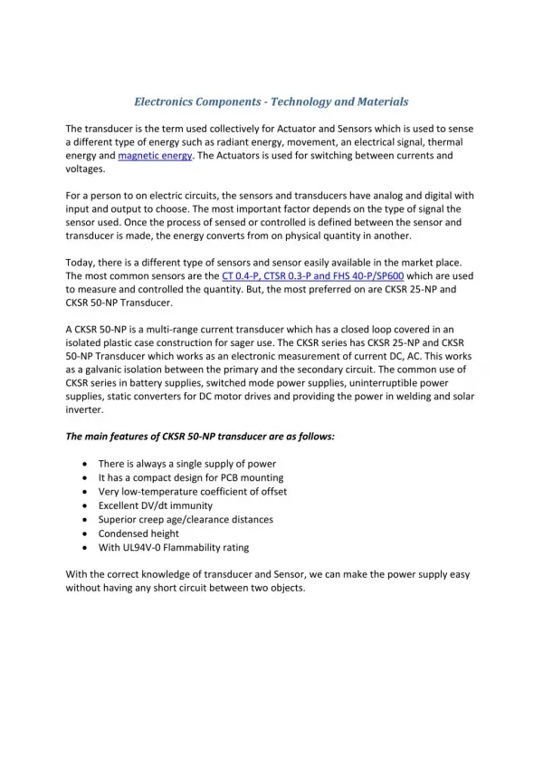
Resistors • The resistor is one of the basic components in electrical circuits. Resistors are used where the resistance of the circuit needs adjustment, typically for limiting the electrical current between two nodes. • The majority of resistors in a circuit have fixed resistance values, however potentiometers may be used to allow adjustment of the resistance. One typical application of potentiometers is volume control in audio players.
Resistors • Function of resistors • The function of a resistor in a circuit is described by Ohm's law and depends upon three variables: • The resistance of the resistor, • The voltage difference between its poles • The flow of electrons (current) through the resistor. If two of the three are known, the third can easily be calculated. • Resistors are not polarized, meaning that they can be inserted into a circuit either way around.
Resistance Defined • Resistance is the impediment to the flow of electrons through a conductor • Resistance is Friction to moving electrons • Friction generates heat • All materials exhibit some resistance, even the best of conductors • Resistance is measured in Ohm(s) • From fractions of Ohms to millions of Ohms
Resistance Example • If you rub the palms of your hands together, you will realize that your hands do not move freely across each other. You will also note that while rubbing your hands back and forth, heat is generated. This heat is generated from the friction between your palm surfaces resisting the movement of your hands. Since your palms are resisting the kinetic energy from the movement of your hands, the resistance is converted to heat.. • The same thing happens as electrons try to move through a conductor or other material. The electrons run into things as they move, and each collision causes the electron’s movement to be impeded in some way, and the resulting loss of kinetic energy is converted into heat. In the majority of cases in electronics, this heat is an undesired byproduct. In other cases, the heat is desirable as is the case with a stove top. In still other cases, the generated heat must be moved away from the electronic device to prevent damage to other components. A good example of this would be the fans in a computer. • In summary, resistance is friction toward moving electrons. All materials provide some level of resistance. The unit of resistance is the Ohm. Resistance measurements can be incredibly small to incredibly large.
Wire and Resistance • Wire is usually used to simply carry electricity from one point to another. Electrical wire is usually made of copper but aluminum and even silver and gold are sometimes used. • Notice that as the diameter of the wire increases the gauge number decreases. The electrical resistance decreases with larger diameter wire but increases with length. • The resistance also increases with temperature. • An ohmmeter is used to test the resistance or continuity of a wire.
Resistor Types • Fixed Value • Variable value • Composite resistive material • Wire-wound • Two parameters associated with resistors • Resistance value in Ohms • Power handling capabilities in watts
Resistor Types Defined • Fixed Value- A fixed-value resistor has a series of coloured bands around its body, which signifies the resistor's value and tolerance. • Variable- The resistance value of a variable resistor can be varied between an upper and lower limit.
Ohm’s Law Ohms Law states that the direct current flowing in a conductor is directly proportional to the potential difference between its ends. Ohms Law is usually formulated as E = IR, where: E is the potential difference, or voltage, I is the current, and R is the resistance of the conductor.
Resistors in CircuitsSeries • Looking at the current path, if there is only one path, the components are in series.
Resistors in CircuitsSeries • The main distinction between series and parallel circuits is how many paths the current has available to complete the course from the negative pole of the power source to the positive pole. • In this diagram, all the current from the battery must pass through both resistors. Therefore this circuit a series circuit. • At this point you need to develop the concept of equivalent resistance. Equivalent resistance is what the total resistance would be if you substituted a single resistor the resistors that make up the circuit. • In this case, if the two resistors were to be combined and replaced with a single resistor that had the same resistance, that single resistor would be the equivalent resistor.
Calculating Resistors in Series • It is easy to calculate the equivalent resistance of resistors in series. • Total Resistance is simply the sum of all the resistances. • For example, if R1 is 400 ohms and R2 is 100 ohms, then the equivalent resistance would be 500 ohms. • Another example, if R1 is 50 ohms, R2 is 20k ohms (remember 20k ohms = 20,000 ohms), and R3 is 900 ohms, the equivalent resistance would be 20,950 ohms or 20.95k ohms.
Adding Resistors in Series • For the following exercise, use the series formula for finding total resistance RT = R1 + R2 + R3 + R4…. Remember, Resistance is measured in Ohms and is represented by the Greek symbol Omega Ω.
Resistors in CircuitsParallel • If there is more than one way for the current to complete its path, the circuit is a parallel circuit. • In this case, there are two possible paths. The electrons can go through the left most resistor or the right most resistor. • Since there is more than one path option, this is a parallel circuit.
Resistors in CircuitsParallel • By the very nature of a parallel circuit, the equivalent resistance will be less than any of the single resistors that make up the circuit. • This property makes sense if you think about it. Referring back to the water analogy. If there is more than one hose for the water to flow through, each path has a relatively narrow hose (resistance). • Then what the water sees as it approached the hose openings is not the narrow opening of just one hose, but the sum of all the opening in the hose, which would make it appear that there is one large opening to go through. • That one large opening is like seeing one lower resistance path than the individual hose openings.
Resistors in CircuitsCombination Parallel and Series • If the path for the current in a portion of the circuit is a single path, and in another portion of the circuit has multiple routes, the circuit is a mix of series and parallel.
Resistors in CircuitsParallel and Combination • Let’s start with a relatively simple mixed circuit. Build this using: • R1 = 330 • R2 = 4.7K • R3 = 2.2K R1 R2 R3
Resistors in CircuitsCombination • Take the parallel segment of the circuit and calculate the equivalent resistance: R1 R2 R3