Download
1 / 83
840 likes | 997 Vues
Learn about grain boundaries in microstructure, misorientation distributions, Rodrigues space, and crystallography of boundaries. Understand the impact of symmetry and degrees of freedom on grain boundaries.

E N D
Grain Boundaries, Misorientation Distributions, Rodrigues space, Symmetry 27-750 Texture, Microstructure & Anisotropy, A.D. Rollett Last revised: 31stOct. ‘11
Objectives • Identify the Grain Boundary as an important element of microstructure and focus on the lattice misorientation associated with interfaces. • Define the Misorientation Distribution (MD) or Misorientation Distribution Function (MDF) and describe typical features of misorientation distributions and their representations. • Describe the crystallography of grain boundaries, using the Rodrigues-Frank vector [Frank, F. (1988), “Orientation mapping.” Metallurgical Transactions19A 403-408]. • Describe the effect of symmetry on the Rodrigues space; also the shape of the space (i.e. the fundamental zone) required to describe a unique set of grain boundary types in Rodrigues space, axis-angle space and Euler space. • The discussion provided here is entirely in terms of cubic crystal symmetry. Obviously the details change for different classes of crystal symmetry. • Overall objective of the discussion of grain boundaries is to illustrate the power of gathering data on a statistical basis, which complements the more traditional approach of studying high symmetry boundaries in the transmission electron microscope.
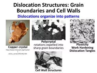
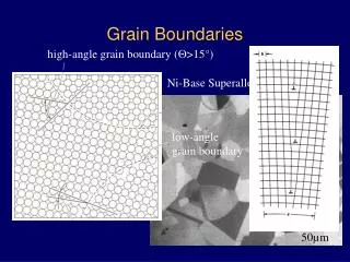
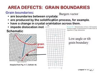
Grain Boundaries • Where crystals or grains join together, the crystal lattice cannot be perfect and therefore a grain boundary exists. At the atomistic scale, each boundary is obvious as a discontinuity in the atomic packing. In most crystalline solids, a grain boundary is very thin (one/two atoms). Disorder (broken bonds) unavoidable for geometrical reasons; therefore large excess free energy (0.1 - 1 J.m-2). http://jolisfukyu.tokai-sc.jaea.go.jp/fukyu/tayu/ACT02E/06/0603.htm
Rotations at a Grain Boundary z gB In terms of orientations: rotate back from position Ato the reference position.Then rotate to position B.Compound (“compose”)the two rotations to arriveat the net rotation betweenthe two grains. y gA-1 referenceposition:(001)[100] x Net rotation = gBgA-1 NB: these are passive rotations
Misorientation • Definition of misorientation†: given two orientations (grains, crystals), the misorientation is the rotation required to transform tensor quantities (vectors, stress, strain) from one set of crystal axes to the other set [passive rotation]. • Alternate [active rotation*]: given two orientations (grains, crystals), the misorientation is the rotation required to rotate one set of crystal axes into coincidence with the other crystal (based on a fixed reference frame). * For the active rotation description, the natural choice of reference frame is the set of sample axes. Expressing the misorientation in terms of sample axes, however, will mean that the associated misorientation axis is unrelated to directions in either crystal. In order for the misorientation axis to relate to crystal directions, one must adopt one of the crystals as the reference frame. Confused?! Study the slides and examples that follow! † In some texts, the word disorientation (as opposed to misorientation) means the smallest physically possible rotation that will connect two orientations. The idea that there is any choice of rotation angle arises because of crystal symmetry: by re-labeling axes (in either crystal), the net rotation changes.
Why are grain boundaries interesting? • Grain boundaries vary a great deal in their characteristics (energy, mobility, chemistry). • Many properties of a material - and also processes of microstructural evolution - depend on the nature of the grain boundaries. • Materials can be made to have good or bad corrosion properties, mechanical properties (creep) depending on the type of grain boundaries present. • Some grain boundaries exhibit good atomic fit and are therefore resistant to sliding, show low diffusion rates, low energy, etc.
Degrees of (Geometric) Freedom • Grain boundaries have 5 degrees of freedom in terms of their macroscopic geometry: either 3 parameters to specify a rotation between the lattices plus 2 parameters to specify the boundary plane; or 2 parameters for each boundary plane on each side of the boundary (total of 4) plus a twist angle (1 parameter) between the lattices. • In addition to the macroscopic degrees of freedom, grain boundaries have 3 degrees of microscopic freedom (not considered here). The lattices can be translated in the plane of the boundary, and they can move towards/away from each other along the boundary normal. • If the orientation of a boundary with respect to sample axes matters (e.g. because of an applied stress, or magnetic field), then an additional 2 parameters must be specified.
1 / 2 / 3 / 5 -parameter GB Character Distributions http://mimp.materials.cmu.edu 5-parameterGrain Boundary Character Distribution – “GBCD”. Each misorientation type expands to a stereogram that shows variation in frequency of GB normals. 1-parameterMisorientationangle only. “Mackenzie plot” 2-parameterGrain Boundary Plane Distribution – “GBPD”. Shows variation in frequency of GB normals only, averaged over misorientation. S3 3-parameterMisorientationDistribution“MDF” Rodrigues-Frank space↵ S9 Nisurface energy [Foiles] Origin Example: Bi-doped Ni
Boundary Type • There are several ways of describing grain boundaries. • A traditional method (in materials science) uses the tilt-twist description. • A twist boundary is one in which one crystal has been twisted about an axis perpendicular to the boundary plane, relative to the other crystal. • A tilt boundary is one in which one crystal has been twisted about an axis that lies in the boundary plane, relative to the other crystal. • More general boundaries have a combination of tilt and twist. • The approach specifies all five degrees of freedom. • Contrast with more recent (EBSD inspired) method that describes only the misorientation between the two crystals. • The Grain Boundary Character Distribution, GBCD, method, developed at CMU, uses misorientation+normal to characterize grain boundaries.
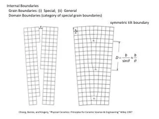
Tilt versus Twist Boundary Types • Tilt boundary is a rotation about an axis in the boundary plane. Thus the misorientation axis is perpendicular to the GB normal. • Twist boundary is a rotation about an axis perpendicular to the plane. Thus the misorientation axis is parallel to the GB normal. Grain A Grain B Tilt Boundary Grain Boundary Grain A Grain B Twist Boundary NB: the tilt or twist angle is not necessarily the same as the minimum misorientation angle (although for low angle boundaries, it typically is so).
How to construct a grain boundary • There are many ways to put together a grain boundary. • There is always a common crystallographic axis between the two grains: one can therefore think of turning one piece of crystal relative to the other about this common axis. This is the misorientation concept. A further decision is required in order to determine the boundary plane. • Alternatively, one can think of cutting a particular facet on each of the two grains, and then rotating one of them to match up with the other. This leads to the tilt/twist concept. • The choice of the particular facet defines the GB normal, and the rotation defines the misorientation. http://www.lce.hut.fi/research/eas/nanosystems/proj_gb/
Differences in Orientation • Preparation for the math of misorientations: the difference in orientation between two grains is a rotation, just as an orientation is the rotation that describes a texture component. • Convention: we use different methods (axis-angle , or Rodriguesvectors) to describe GB misorientation than we do for texture. This is because the rotation axis is often important in terms of its crystallographic alignment (by contrast to orientations, where it is generally of minor interest). • Note that we could use Euler angles for everything, – see for example Zhao, J. and B. L. Adams (1988). "Definition of an asymmetric domain for intercrystalline misorientation in cubic materials in the space of Euler angles." ActaCrystallographicaA44: 326-336.
Alternate Diagram TJACB gB gBgA-1 gD gC gA TJABC
Switching Symmetry gB ∆g=gBgA-1 gAgB-1 gA Switching symmetry:A to B is indistinguishable from B to A because there is no difference in grainboundary structure
Representations of Misorientation • What is different from Texture Components? • Miller indices not useful (except for describing the misorientation axis). • Euler angles can be used but untypical. • Reference frame is usually the crystal lattice, not the sample frame. • Application of symmetry is different (no sample symmetry!)
Grain Boundaries vs. Texture • Why use the crystal lattice as a frame? Grain boundary structure is closely related to the rotation axis, i.e. the common crystallographic axis between the two grains. • The crystal symmetry applies to both sides of the grain boundary; in order to put the misorientation into the fundamental zone (or asymmetric unit) two sets of 24 operators (for cubic symmetry) with the switching symmetry must be used. However only one set of 24 symmetry operators are needed to find the minimum rotation angle. • “Switching symmetry” is explained on a later slide.
Disorientation • Thanks to the cubic crystal symmetry, no two cubic lattices can be different by more than ~62.8°. • Combining two orientations can lead to a rotation angle as high as 180°: applying crystal symmetry operators decreases the required rotation angle. • Disorientation:= (is defined as) the minimum rotation angle between two lattices with the misorientation axis located in the Standard Stereographic Triangle.
Grain Boundary Representation • Axis-angle representation: axis is the common crystal axis (but it is also possible to describe the axis in the sample frame); angle is the rotation angle, q. • 3x3 Rotation matrix, ∆g=gBgAT. • Rodrigues vector: 3 component vector whose direction is the axis direction and whose length = tan(q /2).
MD for Annealed Copper 2 peaks: 60°<111>, and 38°<110> Kocks, Ch.2
Misorientation Distributions • The concept of a Misorientation Distribution (MD, MODF or MDF) is analogous to an Orientation Distribution (OD or ODF). • Relative frequency in the space used to parameterize misorientation, e.g. 3 components of Rodrigues vector, f(R1,R2,R3), or 3 Euler angles f(f1,F,f2) or axis-angle f(, n). • Probability density (but normalized to units of Multiples of a Uniform Density) of finding a given misorientation in a certain range of misorientation, d∆g (specified by all 3 parameters), is given by f(d∆g). • As before, when the word “function” is included in a name, this implies that a continuous mathematical function is available, such as obtained from a series expansion (with generalized spherical harmonics).
Area Fractions • Grain Boundaries are planar defects therefore we should look for a distribution of area (or area per unit volume, SV). • Later we will define the Grain Boundary Character Distribution (GBCD) as the relative frequency of boundaries of a given crystallographic type. • Fraction of area within a certain region of misorientation space, ∆W, is given by the MDF, f, where W0 is the complete space:
Normalization of MDF • If boundaries are randomly distributed then MDF has the same value everywhere, i.e. 1 (since a normalization is required). • Normalize by integrating over the space of the 3 parameters (exactly as for ODF, except that the range of the parameters is different, in general). Thus the MDF is not a true probability density function in the statistical sense. • If Euler angles used, the same equation applies (but one must adjust the normalization constant for the size of the space that is actually used):
Estimation of MDF from ODF • The EBSD softwares often refer to a “texture-based MDF”. • One can always estimate the misorientations present in a material based on the texture. If grains are inserted at random, then the probability of finding a given boundary/misorientation type is the sum of all the possible combinations of orientations that give rise to that misorientation. • Therefore one can estimate the MDF, based on an assumption of randomly placed orientations, drawn from the ODF, thus: • This texture-derived estimate is exactly the texture-based MDF mentioned above. It can be used to normalize the MDF obtained by characterizing grain boundaries in an EBSD map.
Differences in Orientation • Preparation for the math of misorientations: the difference in orientation between two grains is a rotation just as is the rotation that describes a texture component. • Careful! The application of symmetry is different from orientations because crystal symmetry applies to both sides of the relationship (but not sample symmetry), • Convention: we use different methods (Rodrigues vectors) to describe g.b. misorientation than for texture (but we could use Euler angles for everything, for example).
Example: Twin Boundary in fcc The energy of the coherent twin GB is exceptionally low because of the the perfect atomic fit between the two surfaces. <111> rotation axis, common to both crystals q=60° CSL: 3 Axis/Angle: 60°<111> Rodrigues: [1/3, 1/3, 1/3] Quaternion: [1/2, 1/2, 1/2, 1/2] MATRIX REPRESENTATION: [ 0.667 0.667 -0.667 ] [ -0.333 0.667 0.667 ] [ 0.333 -0.333 0.667 ] Porter & Easterling fig. 3.12/p123 There is also an exceptionally low energy “twin” in bcc metals, which is 60°<111> with a {112} normal
Coherent vs. Incoherent Twin • The word “coherent” refers to coherency or matching of atoms across an interface. When two close-packed 111 planes (in fcc materials) are placed in contact, there are two positions (relative rotations, with in-plane adjustments) that provide exact atom matching. One results in no boundary at all, and the other has a 60° misorientation about the interface normal. This latter is the “coherent twin”. • Any interface with the same misorientation but a different normal than 111 is an incoherent twin boundary because the atoms do not fit together exactly. • Fcc metals with medium to low stacking energy commonly exhibit high fractions of coherent twin boundaries or “annealing twins”. • The word “twin” is also used for deformation twins. In the most general sense it refers to pairs of orientations related by a mirror; centro-symmetry allows a proper rotation to accomplish the same relationship. We return to this topic when we discuss Coincident Site Lattice (CSL) misorientations. • This will be addressed in more detail elsewhere. • See: Olmsted, D. L., S. M. Foiles, et al. (2009). "Survey of computed grain boundary properties in face-centered cubic metals: I. Grain boundary energy." Actamaterialia57: 3694-3703.
Grain Boundary Representation • Axis-angle representation: axis is the common crystal axis (but could also describe the axis in the sample frame); angle is the rotation angle, q. • 3x3 Rotation matrix, ∆g=gBgA-1. • Rodrigues vector: 3 component vector whose direction is themisorientation axis direction and whose length is equal to the tangent of 1/2 of the rotation angle, q:R = tan(q/2)v, v is a unit vector representing the rotation axis.
The crystal symmetry pre-multiplies the orientation matrix ∆g =(OcgB)(OcgA)-1= OcgBgA-1Oc-1 = OcgBgA-1Oc. Note the presence of symmetry operators pre- & post-multiplying the misorientation; no inverse is needed for a symmetry operator (member of a finite group). Misorientation +Symmetry Reminder from lecture on volume fractions
Axis transformations:24 independent operators (for cubic) present on either side of the misorientation. Two equivalents from switching symmetry, i.e. the fact that there is no (physical) difference between passing from grain A to grain B, versus passing from grain B to grain A. Number of equivalents = 24x24x2=1152. Symmetry: how many equivalent representations of misorientation? Reminder from lecture on volume fractions
Rodrigues vector, contd. • Many of the boundary types that correspond to a high fraction of coincident lattice sites (i.e. low sigma values in the CSL model) occur on the edges of the Rodrigues space. • CSL boundaries have simple values, i.e. components are reciprocals of integers: e.g. twin in fcc = (1/3,1/3,1/3) 60° <111> 3. The “sigma number” is the reciprocal of the fraction of common (coincident) sites between the lattices of the two grains. • RF space is also useful for texture representation. • CSL theory of grain boundaries will be explained in a later lecture: for now, think of a CSL type as a particular (mathematically singular) misorientation for which good atomic fit may be expected (and therefore special properties). A list of values for CSL types up to =29 is provided in the supplemental slides. • How does one compute how near a GB is to a CSL boundary type? The answer is to first make sure that both are in the same FZ, then compute the misorientation between them, in exactly the same way as for a pair of orientations. This is described in more detail in the lecture on CSLs.
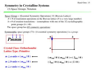
Examples of symmetry operators in various parameterizations • Diad on zor C2z, or L0012: • Triad about [111], or 120°-<111>, or, L1113: Note how infinity is a common value in the Rodrigues vectors that describe 180° rotations. This makes Rodrigues vectors awkward to use from a numerical perspective and is one reason why (unit) quaternions are used.
Cubic Crystal Symmetry Operators The numerical values of these symmetry operators can be found at:http://neon.materials.cmu.edu/texture_subroutines: quat.cubic.symm etc.
Symmetry in Rodrigues space • Demonstration of symmetry elements as planes • Illustration of action of a symmetry element -90° about [100] which is the Rodrigues vector [-1,0,0]. • Order of application of elements to active rotations. • In this case, it is useful to demonstrate that any vector on the plane 1 = √2-1 is mapped onto the plane 1 = -1(√2-1).
Example: 90° <100> • Consider the vector [√,2,3] acted on by the operator [-1,0,0], i.e. -90° about [100]:rC = (rA, rB) = {rA + rB - rAxrB}/{1 - rA•rB} Cross product term Scalar product term Any point outside the plane defined by R1 = √ will be equivalent to a point inside the plane R1 = -(√). Thus this pair of planes define edges of the fundamental zone.
Action of 90° about [100] Inspection of the result shows that any point on the plane 1 = √2-1 is mapped onto a new, symmetry-related point lying on the plane 1 = -1*(√2-1), regardless of the values of the other two parameters of the Rodrigues vector. The re-appearance of a point as it passes through a symmetry element at a different surface of the fundamental zone has been likened to the umklapp process for electrons.
Symmetry planes in RF space • The effect of any symmetry operator in Rodrigues space is to insert a dividing plane in the space. If R (= tan(q/2)v) is the vector that represents the symmetry operator (v is a unit vector), then the dividing plane is y + tan(±q/4)v, where y is an arbitrary vector perpendicular to v. • This arises from the geometrical properties of the space (extra credit: prove this property of the Rodrigues-Frank vector).
Fundamental Zone, FZ • By setting limits on all the components (and confining the axis associated with an RF vector to the SST) we have implicitly defined a Fundamental Zone. • The Fundamental Zone is simply the set of (mis-)orientations for which there is one unique representation for any possible misorientation. This unique representation is sometimes termed the disorientation. • Note: the standard 90x90x90 region in Euler space for orientations contains 3 copies of the FZ for cubic-orthorhombic symmetry. The 90x90x90 region in Euler space for misorientations contains 48 copies of the FZ for cubic-cubic symmetry. Just as with orientations, so for misorientations, we can apply group theory to compute the size of the (mis-)orientation space needed for a FZ.
Size, Shape of the Fundamental Zone • We can use some basic information about crystal symmetry to set limits on the size of the FZ. • Clearly in cubic crystals we cannot rotate by more than 45° about a <100> axis before we encounter equivalent rotations by going in the opposite direction; this sets the limit of R1=tan(22.5°)=√2-1. • This defines a plane perpendicular to the R1 axis.
Size, Shape of the Fundamental Zone • Similarly, we cannot rotate by more than 60° about <111>, which sets a limit of (1/3,1/3,1/3) along the <111> axis, or √{R12+R22+R32}=tan(30°)=1/√3. Note that this is the limit on the length of the Rodrigues vector // 111. In general, the limit is expressed as the equation of a plane, R1+R2+R3=1. • Symmetry operators can be defined in Rodrigues space, just as for matrices or Euler angles. However, we typically use unit quaternions for operations with rotations because some of the symmetry operators, when expressed as Rodrigues vectors, contain infinity as a coefficient, which is highly inconvenient numerically! • The FZ for grain boundaries in cubic materials has the shape of a truncated pyramid.
Delimiting planes • For the combination of O(222) for orthorhombic sample symmetry and O(432) for cubic crystal symmetry, the limits on the Rodrigues parameters are given by the planes that delimit the fundamental zone. • These include (for cubic crystal symmetry with O(432)): - six octagonal facets orthogonal to the <100> directions, at a distance of tan(π/8) (=√2-1) from the origin, and - eight triangular facets orthogonal to the <111> directions at a distance of tan(π/6) (=√3-1) from the origin. • The sample symmetry operators appear as planes that intersect the origin, with normals parallel to the associated rotation axis. A slightly odd feature of RF-space (not well explained in the books) is that each 2-fold operator (diad) excludes ½ the space. If one were to literally divide the space by two perpendicular to each direction, then one would be left with only an octant, which would contain only 1/8 the volume of the original. However, one has to recall that combining any pair of diads (from O(222)) leads the same result and adding a third diad makes no difference. Strictly speaking, one should keep the all-positive octant and the all-negative octant. It is convenient for representation to keep two adjacent octants, as shown by Neumann (next slide). This “trick” has the effect of making the y-axis look different from x and z, but this is a visual convenience.
Symmetry planes in RF space 4-fold axis on <100> 3-fold axis on <111> Cubic crystal symmetry,no sample symmetry Cubic-cubic symmetry Cubic-orthorhombic Neumann, P. (1991). "Representation of orientations of symmetrical objects by Rodrigues vectors." Textures and Microstructures 14-18: 53-58
R1+R2+R3=1 l =111 l =100 (√2-1,√2-1)) (√2-1,0) l =110 Truncated pyramid for cubic-cubic misorientations The fundamental zone for grain boundaries between cubic crystals is a truncated pyramid.
Range of Values of RF vector components for grain boundaries in cubic materials • Q. If we use Rodrigues vectors, what range of values do we need to represent grain boundaries? • A. Since we are working with a rotation axis that is based on a crystal direction then it is logical to confine the axis to the standard stereographic triangle (SST). Colored triangle copied from TSLTM software
Shape of RF Space for cubic-cubic z, r3 y, r2 origin x=y=z, r1=r2=r3, [111] x, r1, [100] x=y, r1=r2[110] Distance (radius) from origin represents the misorientation angle (tan(/2)) Each colored line represents a low-index rotation axis, as in the colored triangle.
Range of RF vector components • r1 corresponds to the component //[100];r2 corresponds to the component //[010];r3 corresponds to the component //[001]; • r1 > r2 > r3 > 0 • 0 £ r1£ (√2-1) • r2 £ r1 • r3 £ r2 • r1 + r2 + r3£ 1 45° rotation about <100> 60° rotation about <111>
Alternate Notation: (R1 R2 R3) • R1 corresponds to the component //[100]; R2 corresponds to the component //[010]; R3 corresponds to the component //[001]; • R1 > R2 > R3 > 0 • 0 £ R1£ (√2-1) • R2 £ R1 • R3 £ R2 • R1 + R2 + R3£ 1
Sections through RF-space • For graphical representation, the R-F space is typically sectioned parallel to the 100-110 plane. • Each triangular section has R3=constant. • Most of the special CSL relationships lie on the 100, 110, 111 lines. base of pyramid
<111> RF-space r1 + r2 + r3£ 1 <110> Exercise: show that the largest possible misorientation angle corresponds to the point marked by o. Based on the geometry of the fundamental zone, calculate the angle (as an inverse tangent). Hint: the answer is in Frank’s 1988 paper on Rodrigues vectors. <111> <100>, r1 <110> <100>, r1 [Randle]
Density of points in RF space • The variation in the volume element with magnitude of the RF vector (i.e.with misorientation angle) is such that the density of points decreases slowly with distance from the origin. • For a random distribution, low angle boundaries are rare, so in a one-parameter distribution based on misorientation angle, the frequency increases rapidly with angle up to the maximum at 45°. Think of integrating the volume in successive spherical layers (layers of an onion). The outer layers have larger volumes than the inner layers. • Mackenzie, J. K. (1958). “Second paper on statistics associated with the random orientation of cubes.” Biometrica45: 229-240.
Mackenzie Distribution for cubic-cubic • Frequency distribution with respect to disorientation angle for randomly distributed grain boundaries. • This result can be easily obtained by generating sets of random orientations, and applying crystal symmetry to find the minimum rotation angle for each set, then binning, normalizing (to unit area) and plotting. Morawiec A, Szpunar JA, Hinz DC. Acta metall. mater. 1993;41:2825. The peak at 45° is associated with the 45° rotation limit on the <100> axis - again, think of integrating over a spherical shell associated with each value of the misorientation angle.