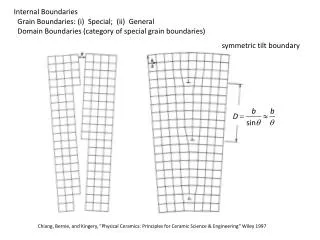
Misorientations and Grain Boundaries
Misorientations and Grain Boundaries. 27-750, Advanced Characterization & Microstructural Analysis A.D. Rollett, P.N. Kalu. Last revised: 9 th June, 2009. Objectives. Introduce grain boundaries as a microstructural feature of particular interest.

Misorientations and Grain Boundaries
E N D
Presentation Transcript
Misorientations and Grain Boundaries 27-750, Advanced Characterization & Microstructural Analysis A.D. Rollett, P.N. Kalu Last revised: 9th June, 2009
Objectives • Introduce grain boundaries as a microstructural feature of particular interest. • Describe misorientation, why it applies to grain boundaries and orientation distance, and how to calculate it, with examples. • Define the Misorientation Distribution Function (MDF): the MDF can be used, for example, to quantify how many grain boundaries of a certain type are present in a sample, where “type” is specified by the misorientation.
References • A. Sutton and R. Balluffi, Interfaces in Crystalline Materials, Oxford, 1996. • V. Randle & O. Engler (2000). Texture Analysis: Macrotexture, Microtexture & Orientation Mapping. Amsterdam, Holland, Gordon & Breach. • Frank, F. (1988). “Orientation mapping.” Metallurgical Transactions 19A: 403-408. • H. Grimmer, Acta Cryst., A30, 685 (1974) • V. Randle & O. Engler (2000). Texture Analysis: Macrotexture, Microtexture & Orientation Mapping. Amsterdam, Holland, Gordon & Breach. • S. Altmann (2005 - reissue by Dover), Rotations, Quaternions and Double Groups, Oxford. • A. Morawiec (2003), Orientations and Rotations, Springer (Europe).
Misorientation • Definition of misorientation†: given two orientations (grains, crystals), the misorientation is the rotation required to transform tensor quantities (vectors, stress, strain) from one set of crystal axes to the other set [passive rotation]. • Alternate [active rotation*]: given two orientations (grains, crystals), the misorientation is the rotation required to rotate one set of crystal axes into coincidence with the other crystal (based on a fixed reference frame). * For the active rotation description, the natural choice of reference frame is the set of sample axes. Expressing the misorientation in terms of sample axes, however, will mean that the associated misorientation axis is unrelated to directions in either crystal. In order for the misorientation axis to relate to crystal directions, one must adopt one of the crystals as the reference frame. Confused?! Study the slides and examples that follow! † In some texts, the word disorientation (as opposed to misorientation) means the smallest physically possible rotation that will connect two orientations. The idea that there is any choice of rotation angle arises because of crystal symmetry: by re-labeling axes (in either crystal), the net rotation changes.
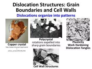
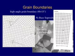
Why are grain boundaries interesting? • Grain boundaries vary a great deal in their characteristics (energy, mobility, chemistry). • Many properties of a material - and also processes of microstructural evolution - depend on the nature of the grain boundaries. • Materials can be made to have good or bad corrosion properties, mechanical properties (creep) depending on the type of grain boundaries present. • Some grain boundaries exhibit good atomic fit and are therefore resistant to sliding, show low diffusion rates, low energy, etc.
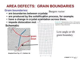
What is a Grain Boundary? • Boundary between two grains. • Regular atomic packing disrupted at the boundary. • In most crystalline solids, a grain boundary is very thin (one/two atoms). • Disorder (broken bonds) unavoidable for geometrical reasons; therefore large excess free energy (0.1 - 1 J.m-2).
Degrees of (Geometric) Freedom • Grain boundaries have 5 degrees of freedom in terms of their macroscopic geometry: either 3 parameters to specify a rotation between the lattices plus 2 parameters to specify the boundary plane; or 2 parameters for each boundary plane on each side of the boundary (total of 4) plus a twist angle (1 parameter) between the lattices. • In addition to the macroscopic degrees of freedom, grain boundaries have 3 degrees of microscopic freedom (not considered here). The lattices can be translated in the plane of the boundary, and they can move towards/away from each other along the boundary normal. • If the orientation of a boundary with respect to sample axes matters (e.g. because of an applied stress, or magnetic field), then an additional 2 parameters must be specified.
Boundary Type • There are several ways of describing grain boundaries. • A traditional method (in materials science) uses the tilt-twist description. • A twist boundary is one in which one crystal has been twisted about an axis perpendicular to the boundary plane, relative to the other crystal. • A tilt boundary is one in which one crystal has been twisted about an axis that lies in the boundary plane, relative to the other crystal. • More general boundaries have a combination of tilt and twist. • The approach specifies all five degrees of freedom. • Contrast with more recent (EBSD inspired) method that describes only the misorientation between the two crystals.
Grain A Grain B Tilt Boundary Grain Boundary Grain A Grain B Twist Boundary Tilt versus Twist Boundary Types • Tilt boundary is a rotation about an axis in the boundary plane. • Twist boundary is a rotation about an axis perpendicular to the plane. NB: the tilt or twist angle is not necessarily the same as the misorientation angle (although for low angle boundaries, it typically is so).
How to construct a grain boundary • There are many ways to put together a grain boundary. • There is always a common crystallographic axis between the two grains: one can therefore think of turning one piece of crystal relative to the other about this common axis. This is the misorientation concept. A further decision is required in order to determine the boundary plane. • Alternatively, one can think of cutting a particular facet on each of the two grains, and then rotating one of them to match up with the other. This leads to the tilt/twist concept.
Differences in Orientation • Preparation for the math of misorientations: the difference in orientation between two grains is a rotation, just as an orientation is the rotation that describes a texture component. • Convention: we use different methods (Rodrigues vectors) to describe g.b. misorientation than for texture (but we could use Euler angles for everything, for example).
Example: Twin Boundary <111> rotation axis, common to both crystals q=60° Porter & Easterling fig. 3.12/p123
Rotations at a Grain Boundary z gB In terms of orientations: rotate back from position Ato the reference position.Then rotate to position B.Compound (“compose”)the two rotations to arriveat the net rotation betweenthe two grains. y gA-1 referenceposition:(001)[100] x Net rotation = gBgA-1 NB: these are passive rotations
Alternate Diagram TJACB gB gBgA-1 gD gC gA TJABC
Representations of Misorientation • What is different from Texture Components? • Miller indices not useful (except for axis). • Euler angles can be used but untypical. • Reference frame is usually the crystal lattice, not the sample frame. • Application of symmetry is different (no sample symmetry!)
Grain Boundaries vs. Texture • Why use the crystal lattice as a frame? Grain boundary structure is closely related to the rotation axis, i.e. the common crystallographic axis between the two grains. • The crystal symmetry applies to both sides of the grain boundary; in order to put the misorientation into the fundamental zone (or asymmetric unit) two sets of 24 operators (for cubic symmetry) with the switching symmetry must be used. However only one set of 24 symmetry operators are needed to find the minimum rotation angle. • “Switching symmetry” is explained on a later slide.
Disorientation • Thanks to the crystal symmetry, no two cubic lattices can be different by more than ~62.8°. • Combining two orientations can lead to a rotation angle as high as 180°: applying crystal symmetry operators decreases the required rotation angle. • Disorientation:= (is defined as) the minimum rotation angle between two lattices with the misorientation axis located in the Standard Stereographic Triangle.
Grain Boundary Representation • Axis-angle representation: axis is the common crystal axis (but it is also possible to describe the axis in the sample frame); angle is the rotation angle, q. • 3x3 Rotation matrix, ∆g=gBgAT. • Rodrigues vector: 3 component vector whose direction is the axis direction and whose length = tan(q /2).
How to Choose the Misorientation Angle: matrix • If the rotation angle is the only criterion, then only one set of 24 operators (cubic) need be applied: sample versus crystal frame is indifferent because the angle (from the trace of a rotation matrix) is invariant under axis transformation. Note: taking absolute value of the misorientation angle accounts for switching symmetry
How to Choose the Misorientation Angle: quaternions • This algorithm is valid only for cubic-cubic misorientations and for obtaining only the angle (not the axis). • Arrange q4 q3 q2 q1 0.Choose the maximum value of the fourth component, q4’, from three variants as follows:[i] (q1,q2,q3,q4)[ii] (q1-q2, q1+q2, q3-q4, q3+q4)/√2[iii] (q1-q2+q3-q4, q1+q2-q3-q4, -q1+q2+q3-q4, q1+q2+q3+q4)/2 • Reference: Sutton & Balluffi, section 1.3.3.4; see also H. Grimmer, Acta Cryst., A30, 685 (1974) for more detail.
Rotation Axis, Angle gB ∆g=gBgA-1 gAgB-1 gD gC gA Switching symmetry:A to B is indistinguishable from B to A rotation axis, common to both crystals
Switching Symmetry • What do we mean by switching symmetry? • The idea is that going from grain A to grain B makes no difference to the physical nature of the boundary. Therefore we consider the two descriptions to be physically equivalent. • The mathematical descriptions are different, however. Therefore we have to describe the set of equivalent misorientations as the union of the forward and backward sets. • Also, collapsing the descriptions into a fundamental zone with only one unique descriptor of each misorientation requires care with the shape and symmetry elements used.
Crystal vs Sample Frame Components ofthe rotation axisare always (1/√3,1/√3,1/√3) inthe crystal frame:in the sample framethe componentsdepend on theorientations ofthe grains. z gB y gA-1 q=60° referenceposition:(001)[100] x
Worked Example • In this example, we take a pair of orientations that were chosen to have a 60°<111> misorientation between them (rotation axis expressed in crystal coordinates). In fact the pair of orientations are the two sample symmetry related Copper components, which are twin related. • We calculate the 3x3 Rotation matrix for each orientation, gA and gB, and then form the misorientation matrix, ∆g=gBgA-1. • From the misorientation matrix, we calculate the angle, = cos-1(trace(∆g)-1)/2), and the rotation axis. • In order to find the smallest possible misorientation angle, we have to apply crystal symmetry operators, O, to the misorientation matrix, O∆g, and recalculate the angle and axis. • First, let’s examine the result….
Worked Example angles.. 90. 35.2599983 45. angles.. 270. 35.2599983 45. 1st Grain: Euler angles: 90. 35.2599983 45. 2nd Grain: Euler angles: 270. 35.2599983 45. 1st matrix: [ -0.577 0.707 0.408 ] [ -0.577 -0.707 0.408 ] [ 0.577 0.000 0.817 ] 2nd matrix: [ 0.577 -0.707 0.408 ] [ 0.577 0.707 0.408 ] [ -0.577 0.000 0.817 ] Product matrix for gA X gB^-1: [ -0.667 0.333 0.667 ] [ 0.333 -0.667 0.667 ] [ 0.667 0.667 0.333 ] MISORI: angle= 60. axis= 1 1 -1 {100} pole figures + Note that the misorientation axis is // 1 1 -1, which is also the sample-1 (X) axis
Detail Output Symmetry operator number 11 Product matrix for gA X gB^-1: [ -0.333 0.667 -0.667 ] [ 0.667 0.667 0.333 ] [ 0.667 -0.333 -0.667 ] Trace = -0.333261013 angle = 131.807526 Symmetry operator number 12 Product matrix for gA X gB^-1: [ 0.667 0.667 0.333 ] [ 0.667 -0.333 -0.667 ] [ -0.333 0.667 -0.667 ] Trace = -0.333261073 angle = 131.807526 Symmetry operator number 13 Product matrix for gA X gB^-1: [ -0.333 0.667 -0.667 ] [ -0.667 -0.667 -0.333 ] [ -0.667 0.333 0.667 ] Trace = -0.333261013 angle = 131.807526 Symmetry operator number 14 Product matrix for gA X gB^-1: [ -0.667 -0.667 -0.333 ] [ -0.667 0.333 0.667 ] [ -0.333 0.667 -0.667 ] Trace = -1. angle = 180. Symmetry operator number 15 Product matrix for gA X gB^-1: [ 0.333 -0.667 0.667 ] [ -0.667 -0.667 -0.333 ] [ 0.667 -0.333 -0.667 ] Trace = -1. angle = 180. Symmetry operator number 16 Product matrix for gA X gB^-1: [ -0.667 -0.667 -0.333 ] [ 0.667 -0.333 -0.667 ] [ 0.333 -0.667 0.667 ] Trace = -0.333260953 angle = 131.807526 Symmetry operator number 23 Product matrix for gA X gB^-1: [ -0.667 -0.667 -0.333 ] [ -0.333 0.667 -0.667 ] [ 0.667 -0.333 -0.667 ] Trace = -0.666522026 angle = 146.435196 Symmetry operator number 24 Product matrix for gA X gB^-1: [ -0.333 0.667 -0.667 ] [ 0.667 -0.333 -0.667 ] [ -0.667 -0.667 -0.333 ] Trace = -0.999999881 angle = 179.980209 MISORI: angle= 60. axis= 1 1 MISORI: angle= 60. axis= 1 1 -1-1 Symmetry operator number 5 Product matrix for gA X gB^-1: [ -0.667 -0.667 -0.333 ] [ 0.333 -0.667 0.667 ] [ -0.667 0.333 0.667 ] Trace = -0.666738987 angle = 146.446442 Symmetry operator number 6 Product matrix for gA X gB^-1: [ 0.667 0.667 0.333 ] [ 0.333 -0.667 0.667 ] [ 0.667 -0.333 -0.667 ] Trace = -0.666738987 angle = 146.446442 Symmetry operator number 7 Product matrix for gA X gB^-1: [ 0.667 -0.333 -0.667 ] [ 0.333 -0.667 0.667 ] [ -0.667 -0.667 -0.333 ] Trace = -0.333477974 angle = 131.815872 Symmetry operator number 8 Product matrix for gA X gB^-1: [ 0.667 -0.333 -0.667 ] [ -0.333 0.667 -0.667 ] [ 0.667 0.667 0.333 ] Trace = 1.66695571 angle = 70.5199966 Symmetry operator number 9 Product matrix for gA X gB^-1: [ 0.333 -0.667 0.667 ] [ 0.667 -0.333 -0.667 ] [ 0.667 0.667 0.333 ] Trace = 0.333477855 angle = 109.46682 Symmetry operator number 10 Product matrix for gA X gB^-1: [ -0.333 0.667 -0.667 ] [ -0.667 0.333 0.667 ] [ 0.667 0.667 0.333 ] Trace = 0.333477855 angle = 109.46682 Symmetry operator number 17 Product matrix for gA X gB^-1: [ 0.333 -0.667 0.667 ] [ 0.667 0.667 0.333 ] [ -0.667 0.333 0.667 ] Trace = 1.66652203 angle = 70.533165 Symmetry operator number 18 Product matrix for gA X gB^-1: [ 0.667 0.667 0.333 ] [ -0.667 0.333 0.667 ] [ 0.333 -0.667 0.667 ] Trace = 1.66652203 angle = 70.533165 Symmetry operator number 19 Product matrix for gA X gB^-1: [ 0.333 -0.667 0.667 ] [ -0.667 0.333 0.667 ] [ -0.667 -0.667 -0.333 ] Trace = 0.333044171 angle = 109.480003 Symmetry operator number 20 Product matrix for gA X gB^-1: [ 0.667 -0.333 -0.667 ] [ 0.667 0.667 0.333 ] [ 0.333 -0.667 0.667 ] Trace = 2. angle = 60. Symmetry operator number 21 Product matrix for gA X gB^-1: [ 0.667 0.667 0.333 ] [ -0.333 0.667 -0.667 ] [ -0.667 0.333 0.667 ] Trace = 2. angle = 60. Symmetry operator number 22 Product matrix for gA X gB^-1: [ 0.667 -0.333 -0.667 ] [ -0.667 -0.667 -0.333 ] [ -0.333 0.667 -0.667 ] Trace = -0.666522205 angle = 146.435211 1st matrix: [ -0.691 0.596 0.408 ] [ -0.446 -0.797 0.408 ] [ 0.569 0.100 0.817 ] 2nd matrix: [ 0.691 -0.596 0.408 ] [ 0.446 0.797 0.408 ] [ -0.569 -0.100 0.817 ] Symmetry operator number 1 Product matrix for gA X gB^-1: [ -0.667 0.333 0.667 ] [ 0.333 -0.667 0.667 ] [ 0.667 0.667 0.333 ] Trace = -1. angle = 180. Symmetry operator number 2 Product matrix for gA X gB^-1: [ -0.667 0.333 0.667 ] [ -0.667 -0.667 -0.333 ] [ 0.333 -0.667 0.667 ] Trace = -0.666738808 angle = 146.446426 Symmetry operator number 3 Product matrix for gA X gB^-1: [ -0.667 0.333 0.667 ] [ -0.333 0.667 -0.667 ] [ -0.667 -0.667 -0.333 ] Trace = -0.333477736 angle = 131.815857 Symmetry operator number 4 Product matrix for gA X gB^-1: [ -0.667 0.333 0.667 ] [ 0.667 0.667 0.333 ] [ -0.333 0.667 -0.667 ] Trace = -0.666738927 angle = 146.446442 This set of tables shows each successive result as a different symmetry operator is applied to ∆g. Note how the angle and the axis varies in each case!
Passive Rotations Materials Science g describes an axis transformationfrom sample to crystal axes Active Rotations Solid mechanics g describes a rotation of a crystal from ref. position to its orientation. Basics Passive Rotations (Axis Transformations)Active (Vector) Rotations
Objective • To make clear how it is possible to express a misorientation in more than (physically) equivalent fashion. • To allow researchers to apply symmetry correctly; mistakes are easy to make! • It is essential to know how a rotation/orientation/texture component is expressed in order to know how to apply symmetry operations.
g= Z2XZ1 = g= gf1/001gF100gf2/001= Matrices Passive Rotations (Axis Transformations)Active (Vector) Rotations
So what happens when we express orientations as active rotations in the sample reference frame? The result is similar (same minimum rotation angle) but the axis is different! The rotation axis is the sample [100] axis, which happens to be parallel to a crystal <111> direction. Worked example: active rotations {100} pole figures 60° rotationabout RD
angles.. 90. 35.2599983 45. angles.. 270. 35.2599983 45. 1st Grain: Euler angles: 90. 35.2599983 45. 2nd Grain: Euler angles: 270. 35.2599983 45. 1st matrix: [ -0.577 0.707 0.408 ] [ -0.577 -0.707 0.408 ] [ 0.577 0.000 0.817 ] 2nd matrix: [ 0.577 -0.707 0.408 ] [ 0.577 0.707 0.408 ] [ -0.577 0.000 0.817 ] MISORInv: angle= 60. axis= 1 0 0 Symmetry operator number 1 Product matrix for gB X gA^-1: [ -1.000 0.000 0.000 ] [ 0.000 -1.000 0.000 ] [ 0.000 0.000 1.000 ] Trace = -1. angle = 180. Symmetry operator number 2 Product matrix for gB X gA^-1: [ -0.333 0.000 0.943 ] [ 0.816 -0.500 0.289 ] [ 0.471 0.866 0.167 ] Trace = -0.666738927 angle = 146.446442 Symmetry operator number 3 Product matrix for gB X gA^-1: [ 0.333 0.817 0.471 ] [ 0.817 0.000 -0.577 ] [ -0.471 0.577 -0.667 ] Trace = -0.333477914 angle = 131.815872 ………….. Active rotations example Note that the misorientation axis is still // 1 1 -1, but now the calculation identifies 1 0 0 as the axis, which is the sample-1 (X) axis.
What is stranger, at first sight, is that, as you rotate the two orientations together in the sample frame, the misorientation axis moves with them, if expressed in the reference frame (active rotations). On the other hand, if one uses passive rotations, so that the result is in crystal coordinates, then the misorientation axis remains unchanged. Active rotations
Add 10° to the first Euler angle so that both crystals move together: angles.. 100. 35.2599983 45. angles.. 280. 35.2599983 45. 1st Grain: Euler angles: 90. 35.2599983 45. 2nd Grain: Euler angles: 270. 35.2599983 45. 1st matrix: [ -0.577 0.707 0.408 ] [ -0.577 -0.707 0.408 ] [ 0.577 0.000 0.817 ] 2nd matrix: [ 0.577 -0.707 0.408 ] [ 0.577 0.707 0.408 ] [ -0.577 0.000 0.817 ] MISORInv: angle= 60. axis= 6 1 0 Note the change in the misorientation axis from 100 to 610 because it is expressed in the sample frame! Symmetry operator number 1 Product matrix for gB X gA^-1: [ -1.000 0.000 0.000 ] [ 0.000 -1.000 0.000 ] [ 0.000 0.000 1.000 ] Trace = -1. angle = 180. Symmetry operator number 2 Product matrix for gB X gA^-1: [ -0.478 0.004 0.878 ] [ 0.820 -0.355 0.448 ] [ 0.314 0.935 0.167 ] Trace = -0.666738808 angle = 146.446426 Symmetry operator number 3 Product matrix for gB X gA^-1: [ 0.044 0.824 0.564 ] [ 0.824 0.289 -0.487 ] [ -0.564 0.487 -0.667 ] Trace = -0.333477765 angle = 131.815857 ………….. Active rotations example
Symmetry Operators:Osample OsOcrystal OcNote that the crystal symmetry post-multiplies, and the sample symmetry pre-multiplies. Note the reversal in order of application of symmetry operators! Texture+Symmetry Passive Rotations (Axis Transformations)Active (Vector) Rotations
OcO(432);proper rotations of the cubic point group. OsO(222);proper rotations of the orthorhombic point group. Think of applying the symmetry operator in the appropriate frame: thus for active rotations, apply symmetry to the crystal before you rotate it. Groups: Sample+Crystal Symmetry Passive Rotations (Axis Transformations)Active (Vector) Rotations
Misorientations:∆g=gBgA-1;transform from crystal axes of grain A back to the reference axes, and then transform to the axes of grain B. Misorientations:∆g=gBgA-1;the net rotation from A to B is: rotate first back from the position of grain A and then rotate to the position of grain B. Misorientations Passive Rotations (Axis Transformations)Active (Vector) Rotations
In some texts, misorientation formed from axis transformations is written with a tilde. Standard A->B transformation is expressed in crystal axes. You must verify from the context which type of misorientation is discussed in a text! Standard A->B rotation is expressed in sample axes. Notation Passive Rotations (Axis Transformations)Active (Vector) Rotations
∆g=(Oc gB)(Oc gA)-1= OcgBgA-1Oc-1. Note the presence of symmetry operators pre- & post-multiplying the basic misorientation ∆g=gBgA-1; (gBOc)(gAOc)-1= gBOcOc-1gA-1 = gB OcgA-1. Note the reduction to a single symmetry operator because the symmetry operators belong to the same group! Misorientation+Symmetry Passive Rotations (Axis Transformations)Active (Vector) Rotations
Switching Symmetry gB ∆g=gBgA-1 gAgB-1 Switching symmetry:A to B is indistinguishable from B to A because there is no difference in grainboundary structure gA
If we write down the set of possible misorientations, recognizing the equivalence of forward and backward rotations, we get: {∆g}={∆gAB}U{∆gBA} ={(Oc gB)(Oc gA)-1}U(Oc gA)(Oc gB)-1}= {OcgBgA-1Oc-1}U{OcgAgB-1Oc}. Equivalently in the sample frame: {∆g}={gBgA-1}U{gAgB-1}={(gBOc)(gAOc)-1}U{(gAOc)(gBOc)-1}= {gBOcOc-1gA-1}U{gAOcOc-1gB-1}= {gBOcgA-1}U{gAOcgB-1}. Switching Symmetry, v2 Passive Rotations (Axis Transformations)Active (Vector) Rotations
Axis transformations:24 independent operators present on either side of the misorientation. Two equivalents from switching symmetry. Number of equivalents=24x24x2=1152. Active rotations:Only 24 independent operators present “inside” the misorientation. 2 from switching symmetry. Number of equivalents=24x2=48. Symmetry: how many equivalent representations of misorientation? Passive Rotations (Axis Transformations)Active (Vector) Rotations
Passive<-> Active Just as is the case for rotations, and texture components,gpassive(q,n) = gTactive(q,n),so too for misorientations,
Disorientation Choice? • Disorientation to be chosen to make the description of misorientation unique and thus within the Fundamental Zone (irreducible zone, etc.). • Must work in the crystal frame in order for the rotation axis to be described in crystallographic axes. • Active rotations: write the misorientation as follows in order to express in crystal frame:∆g=(gBOc)-1(gAOc)=OcgB-1gAOc-1.
Disorientation Choice, contd. • Rotation angle to be minimized, and, place the axis in the standard stereographic triangle. • Use the full list of 1152 equivalent representations to find minimum angle, and:u v w 0,where [uvw] is the rotation axis associated with the rotation. • Algorithm: see next slide
Pseudo-code for Disorientation ! Work in crystal (local) frame Calculate misorientation as gBgA-1 For each ith crystal symmetry operator, calculate OigBgA-1 For each jth crystal symmetry operator, calculate OigBgA-1Oj Test the axis for whether it lies in the FZ; repeat for inverse rotation If if does, test angle for whether it is lower than the previous minimum If new min. angle found, retain the result (with indices i & j) endif endif enddo enddo Note that it is essential to test the axis in the outer loop and the angle in the inner loop, because it is often the case that the same (minimum ) angle will be found for multiple rotation axes. The “inverse rotation” can be easily obtained by negating the fourth (cosine) component of the quaternion.
(432) in quaternions quat.symm.cubic file with 24 proper rotations in quaternion form 24 0 0 0 1 1 0 0 0 0 1 0 0 0 0 1 0 0.707107 0 0 0.707107 0 0.707107 0 0.707107 0 0 0.707107 0.707107 -0.707107 0 0 0.707107 0 -0.707107 0 0.707107 0 0 -0.707107 0.707107 0.707107 0.707107 0 0 -0.707107 0.707107 0 0 0 0.707107 0.707107 0 0 -0.707107 0.707107 0 0.707107 0 0.707107 0 -0.707107 0 0.707107 0 0.5 0.5 0.5 0.5 -0.5 -0.5 -0.5 0.5 0.5 -0.5 0.5 0.5 -0.5 0.5 -0.5 0.5 -0.5 0.5 0.5 0.5 0.5 -0.5 -0.5 0.5 -0.5 -0.5 0.5 0.5 0.5 0.5 -0.5 0.5 Cubic point group; proper rotations expressed as quaternions;the first four lines/elements/operators are equivalent to (222) and represent orthorhombic symmetry
Conversions for Axis Matrix representation, a, to axis, [uvw]=v: Rodrigues vector:Quaternion: N.B. the axis is assumed to be from an axis transformation
ID of symmetry operator(s) • For calculations (numerical) on grain boundary character, it is critical to retain the identity of each symmetry operator use to place a given grain boundary in the FZ. • That is, given OcO(432)=Oi{O1,O2,…,O24}one must retain the value of index “i” for subsequent use, e.g. in determining tilt/twist character.
Matrix-twin1 Matrix-twin2 Matrix twin1 twin2 twin1 Matrix twin1-twin2 Successive misorientations • There are problems where one needs to calculate the effect of two successive misorientations, taking into account variants. By “variants” we mean that the second misorientation (twin) can occur on any of the systems related by crystal symmetry. For example, if twinning occurs on more than one system, then the second twin can be physically contained within the first twin but still make a boundary with the original matrix. So, the problem is, how do we calculate the matrix-twin2 misorientation, taking account of crystal symmetry and the possibility of (crystal) symmetry-related variants? g’ g g’’ g’ g
Successive Twins • The key to this problem is to recognize that (a) the order of the two twins/misorientations does not matter, and (b) that one must insert an additional (crystal) symmetry element between the two twins/misorientations. In effect one treats each twin/misorientation (T) as a rotation (or orientation). The same procedure can be used for phase transformations, although one must be careful about the difference between going from phase 1 to phase 2, versus 2 to 1. We obtain a set of physically equivalent orientations, {g”}, starting from a matrix orientation, g, thus: • {g”}= (Oc T2) Oc(Oc T1)g= OcT2 OcT1g. • Note the presence of symmetry operators pre-multiplying, as well the additional symmetry operator in between the two misorientations. This additional symmetry operator is applied in a manner that is equivalent to sample symmetry. • Curiously, the order in which the twins/misorientations are applied does not make any difference. The overall misorientation for matrixtwin1twin2is the same as matrixtwin2twin1. The reason for this not very obvious result lies in the identity between (g1g2)-1 and –g2-g1. See the slides on Rodrigues vectors and quaternions (L10-RFvecs_quats_update-8Jun09.ppt). The consequence of this comes from the switching symmetry equivalence (homophase grain boundaries only) for misorientation. • Be careful that chains of twins (or other transformations) longer than two may not have this property. • Thanks to Nathalie Bozzolo (Univ. Metz) for pointing out this problem. • For a (much) more detailed analysis of twin chains, see papers by Cayron.