Embedded Microcontroller Project: Designing and Troubleshooting with MSP430
This project explores the design and implementation of an embedded system utilizing the MSP430 microcontroller. The team aimed to construct a functional board, power the microcontroller, interface it with an LCD and a chosen sensor, and troubleshoot issues that arose during construction and testing phases. Key challenges included soldering errors, component shortages, and ensuring successful data output on the LCD. Ultimately, the project helped team members gain hands-on experience in embedded systems, circuit troubleshooting, and collaborative problem-solving.

Embedded Microcontroller Project: Designing and Troubleshooting with MSP430
E N D
Presentation Transcript
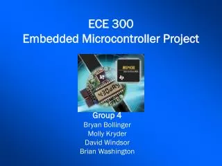
ECE 300Embedded Microcontroller Project Group 4 Bryan Bollinger Molly Kryder David Windsor Brian Washington
Things to pick up along the way • To learn about embedded systems • To gain basic knowledge and working experience with soldering on a small scale • To learn to apply basic troubleshooting knowledge of circuits • To become more familiar with the design process and working in a group environment
Goals What exactly needs to be accomplished? • Construct a functioning board • Power the microcontroller • Successfully Flash the microcontroller • Power and drive the LCD • Interface the board with a sensor • Choose an appropriate device • Connect the sensor to the microcontroller • Scale and display the output
MSP430The microcontroller in question • Low Supply-Voltage Range, 1.8 V to 3.6 V • Lithium and Alkaline voltage range, easy to produce • 12-Bit A/D Converter With Internal Reference, Sample-and-Hold and Autoscan Feature • No need for us to convert analog to digital • Integrated LCD Driver for Up to 160 Segments • No need to write a new interface to drive the LCD • MSP430F449: 60KB+256B Flash Memory, 2KB RAM • Flexibility for coding
Board Construction Team Meeting to practice soldering with the surface mount components and the chip • Resistors • Capacitors • Processor Final Board Construction • A unified soldering method should be decided upon to complete the board, in order to minimize possible soldering error and repair time
Problems • Missing Kit Components -no polarized capacitors, only one MSP430, no voltage converter • Soldering Problems -melted a part of the LCD cover, fused the oscillator crystal leads, first chip soldered incorrectly Mostly minor problems, but the frequency of the problems and the time necessary to retool between them (i.e. time required to obtain replacements etc.) caused initial construction to take much longer than expected
Testing and Troubleshooting • Initial Flashes were not successful • Learned it was an operator error as the Flash Emulation Tool was upside down, another delay • Subsequent Flashes • Reported success but the LCD showed incoherent digits • Shortly thereafter, the LCD showed nothing at all
Testing and Troubleshooting • Possible Causes of Error • Heat Damaged Chip • Mismanufactured Chip • Damaged LCD • Bad Solder Joints • Further study of the board with a voltmeter revealed some bad solder joints which were then repaired • LCD still showed garbage, but at least it showed something
Testing and Troubleshooting • All points on the LCD had continuity to their respective pin on the microprocessor, but still something was not functioning properly • Starting a new board recommended • About this time, another group member began their own board, just in case the current board could not be repaired • The board warranted further testing, so more time was committed to experimentation • An exact-o-knife was used to check the solder joints and traces from the microprocessor to the board • During this process, the LCD managed to show a broken “HELLO”
Testing and Troubleshooting • Adding tiny amounts of solder to each of the pins of the chip resulted in a fully functional board • Another meet to show the board to the team, the LCD would fade in and out, apparently a capacitor problem • Board Finally Successfully Displays “Hello 888” message consistently
Sensor Selection • Several Types of Analog Sensors Group Members Considered • Temperature – Analog Devices 22100, 22103 • Magnetic Field – Sentron CSA1V, AD 22151G • Infrared - Sharp GP2D12 • Ultrasonic Transducer - USONICPNPA • RPM Sensor
More Sensor Selection • Ease of use of the temperature sensor made it very appealing, but there were several models to choose from • The Analog Devices AD22103 is an analog, low power, 3.3V device with a temperature range from 0 to 100 Celsius and it was available in a 3 pin TO-92 Package as opposed to the way many of its cousins and competitors were, an 8 pin package
Interfacing the Sensor and Board • Sensor needed • Power • which was drawn from a spot on the board labeled Vcc which provided 2.85 V • Common ground of the board • a spot for a banana plug lead was drilled and connected to one of the board’s several common grounds • Voltage out to go to the A/D of the MSP430 • again a spot for a banana plug lead was drilled and a wire was run to this location
Analyzing the Code The code provided took the input from the A/D and converted it to a voltage * 100 and stored it in a floating variable called sample. The times 100 comes into play later when displaying results to the LCD The AD22103 Datasheet provided a Transfer Function to convert this voltage into a temperature in degrees Celsius Rearranging the Equation and Solving for TA gives
More Changes • Celsius is the standard temperature scale, but Fahrenheit is easier for most people to relate to • To convert from C to F, simply use the equation below (1.8 * C) + 32 This was an easy modification to the code
A glimpse of the code sample = ADC12MEM6; sample = sample * A; B = (3.3 / 2.85) / .028; sample = sample * B; sample = sample - (.25 / .028)*100; sample = (sample * 1.8) + 3200; lcd_word(sample,2); • Its time to recall the fact that the board is storing and sampling the voltage times 100. Because of this, all constants need to be multiplied by 100. The reason for this is pretty obvious if you look the way in which the LCD driver functions operate. They take the number and perform modulus division on the sample to find out the value of the thousands place, the hundreds place, the tens place, and the ones place and it sends it to the 3rd segment, 2nd segment, 1st segment, and 0th segment respectively.
An Example • What if it were 72.35 degrees in this room? • Then the value of sample after the conversions would be 7,235 so the processor would try to figure out what to send each segment one at a time • Segment 3 = 7,235 / 1000 = 7.235 % 10 = 7.235 + ‘0’ = 7 • Segment 2 = 7,235 / 100 = 72.35 % 10 = 2.35 + ‘0’ = 2 • Segment 1 = 7,235 / 10 = 723.5 % 10 = 3.5 + ‘0’ = 3 • Segment 0 = 7,235 / 1 = 7,235 % 10 = 5 + ‘0’ = 5
Future Changes • Make the board perform an action when a condition is met • Turn on an LED • Make a noise with a small buzzer Such tasks would require only a small amount of additional knowledge of the chip and its interrupt system
Some pictures Back of the board Front of the Board AD22103 – Temp Sensor