Download

1 / 50
540 likes | 1.17k Vues
BCWC Water-Cooled Water Chiller with “oil-free” centrifugal compressors R134a (320-1250kW). Overview. BCWC0320A – 320kW, 90 ton. BCWC0630A – 630kW, 190 ton. Overview. BCWC0950A – 950kW, 270 ton. BCWC1250A – 1250kW, 360 ton. Overview. Overview. MAIN COMPONENTS.

E N D
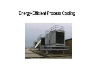
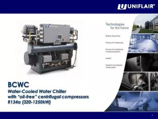
BCWC Water-Cooled Water Chiller with “oil-free” centrifugalcompressors R134a (320-1250kW)
Overview BCWC0320A – 320kW, 90 ton BCWC0630A – 630kW, 190 ton
Overview BCWC0950A – 950kW, 270 ton BCWC1250A – 1250kW, 360 ton
MainComponents - Framework The framework is produced in galvanized sheet steel, with panels painted with epoxy powder paints (color RAL7037) conforming to the ASTM B117 standard. Furthermore, all external screws, nuts, etc are in stainless steel.
MainComponents – ElectricalPanel The panel is built to conform to the 73/23/EEC directive and to its relevant standards. The panel has a general door interlock switch and is housed in an appropriate compartment protected by a panel fastened with ¼ turn screws. The maximum internal temperature of the electrical panel is controlled by a thermostat, and is maintained within parameters which ensure that the panel is protected by the ventilation of external air. Main features: • Conforms to EC standards • General shut off switch • IP42 protection class • 24V auxiliary circuit for the mainboard • 230 V auxiliary circuit for compressor contactors • Fuse protection for each compressor against shortcircuits • Contactors provided for compressors • 1 voltage-free contact for remote signalling of general alarms • Contact for external pump group start-up • EMC filter with harmonic protection • Maximum internal termperature control
MainComponents – R134a The units are equipped with one to four centrifugal compressors with magnetic bearings on a single refrigerant circuit. Since it is, and always has been, an environmentally conscious company, UNIFLAIR has designed these units for use with R134a. It is “ecological” in the sense that it does not harm the ozone layer and contributes minimally to global warming. The TEWI (Total Equivalent Warming Impact) index value is very low, less than 10% with respect to R407C.
MainComponents - Compressor The units in the BCWC range are equipped with the new generation of “oil-free” centrifugal compressors. The “oil-free” technology of the centrifugal compressors is based on the use of magnetic bearings which are integrated with a frequency control (inverter) which enables extremely high rotation speeds to be reached (up to 40000 cycles/min) and to guarantee, at the same time, efficient control at different loads. The integrated soft starter allows progressive start up with low inrush currents and the absence of oil allows more than one compressor to be installed in parallel on each circuit, maximizing efficiency at partial loads (“Tandem” logic). The high efficiency of the compressor is supported by the high efficiency of the flooded evaporator, without the problems associated with the return of oil, given that the system is completely oil-free. The Uniflair UpCO3m control system, by communicating with the internal control of the compressor, results in optimum operation of the chiller. The use of this type of compressor creates a substantial reduction in operating costs and environmental impact as well as guaranteeing high reliability.
MainComponents - Compressor • The impellers operate within a magnetic toroidal field, avoiding mechanical friction. • BCWC units are the ideal choice for: • Optimum efficiency at all load conditions • Maximum reliability • Minimum maintenance • Reduced dimensions and weights • Ultra silent operation
MainComponents - Compressor • 2 stages of centrifugal compression • Speed Control with inverter • Temperature and pressure sensors DC/DC brushless synchronised motor • IGV • Control of the motor and magnetic bearings
MainComponents - Compressor Refrigerant flow The refrigerant enters form the suction slow pressure and low temperature side and is heated. It passes therefore through a valve which has adjustable fins (IGVs) which is usually used in centrifugal compressors to regulate the capacity. The gas is subjected to the first compression by the first stage impeller. The centrifugal forces produced by the rotation of the first impeller increases speed and pressure. The gas is directed at high speed by means of a de-swirl vane to the impeller of the second compression stage and is discharged through the volute. (The speed decreases in the volute and the pressure increases). From here the high pressure gas at a high temperature exits from the discharge exhaust
MainComponents - Compressor Gas compression
MainComponents - Compressor The rotor shaft is held in position with ten separately controlled electro magnetic cushions which continually changes in strength to keep the shaft centrally positioned. The shaft’s position is monitored with ten sensor coils who’s signal is fed back to a digital controller.
MainComponents - Compressor The compressor’s speed adjusts automatically to match the load and current operating conditions so that optimum efficiency is gained The slower the compressor, the greater the efficiency; as speed is reduced, energy consumption is reduced by the cube. The compressor’s speed varies dependent on the conditions. Its operating speeds ranges from 18,000 to 40,000 rpm The inverter is built into the compressor as is the rest of the control system Another advantage of this system is its low starting current, the compressor draws 2 A to start compared to 500 A on a conventional compressor
MainComponents - Compressor Mechanical components
MainComponents - Compressor Electric and Electronic devices
MainComponents - Compressor Control management A closed loop control is used. A closed loop is constantly adjusting the controlled device, sensing the change and making a decision about how much to make the next adjustment. The sensor provides information to the controller (shaft position). Based on the controller’s program, the controller would send a signal to the PWM power module to strengthen the magnetic fields of the magnetic bearings.
MainComponents - Compressor Cooling circuits The stator does produce heat. The Turbocor compressor case has been designed with internal cooling circuits to remove heat from the stator windings (maintaining it to an average temperature of 55°C). The heat from the stator becomes part of the overall cooling load that the compressor must pump.
MainComponents - Compressor Operating field
Delta T BCWC BRWC Traditional Time MainComponents - Compressor Top level performance. An “Oil-free centrifugal compressor is an inverter-driven compressor which only uses the IGV in extreme conditions. BCWC units are able to adapt the cooling capacity to the load with extreme precision. The T at the set-point is ±0,2°C (with load higher that min load)
12 10 8 EER 6 4 2 0 25% 50% 75% 100% BCWC - 630kW BRWC - 630kW Load [%] MainComponents - Compressor Top level performance. BCWC units are able to adapt the cooling capacity of the compressor to the load extremely efficiently. The IPLV and ESEER show that the BCWC efficiency is optimized in all operating conditions.
100.000,0 -100% 90.000,0 -90% 80.000,0 -80% 70.000,0 -70% 60.000,0 -60% -48% Running cost [€/year] 50.000,0 -50% 40.000,0 -40% -38% -38% 30.000,0 -30% -39% 20.000,0 -20% 10.000,0 -10% 0,0 0% 320 650 950 1250 ''oil-free'' compressor chillers Cooling capacity [kW] Screw compressor chillers % Energy saving MainComponents - Compressor Top level performance.
MainComponents - Compressor Top level performance. Current [A] • BCWC units have an integrated soft start. • This means a very low starting current: • 320 kW < 2A • 650 kW < 75A • 950 kW <140A • 1250 kW < 205A Time Current [A] SCR Switch-on Time
MainComponents - Compressor “Oil-free” • "Oil-free" means less cost! • Reduced energy losses in the heat exchangers • Compressors in parallel: optimum performance at partial loads • Flooded evaporator: higher energy efficiency • No oil changes or filter replacements: low maintenance costs • No maintenance of the bearings: low maintenance costs
6000 5000 4000 Weight [Kg] 3000 2000 1000 330 630 950 1250 Models [kW] BCWC BRWC MainComponents - Compressor Reduced dimensions. The BCWC unit is lighter and more compact than any other compressor with the same capacity featuring traditional technology.
100 90 80 Noise power level 70 60 50 40 330 630 950 1250 Frequency [Hz] BCWC BRWC BRWC - LN MainComponents - Compressor Low noise. • Extremely low noise levels • Extremely flat spectrum • Absence of vibrations
100 90 80 Noise power level 70 60 50 40 63Hz 125Hz 250Hz 500Hz 1000Hz 2000Hz 4000Hz 8000Hz Frequency [Hz] BCWC - 630kW BRWC - 630kW BRWC - LN - 630kW MainComponents - Compressor Low noise.
MainComponents - EEV An electronic expansion valve consists of two main parts: the valve itself and the step by step motor. The motor is situated in the upper part of the valve and is connected directly to the body of the valve. The body of the valve, including the valve and the motor, is hermetic and welded in order to eliminate the risk of refrigerant leaks. As is the case for the compressors, the valve motor is in contact with the refrigerant. The electronic expansion valve is equipped with a bipolar, 2-phase motor which has the operating characteristics typical of any step by step motor. It is kept in position until the pulses of current from the driver command it to rotate in one of the two directions. Each impulse commands the rotation of the rotor for one step, and it is rotated for a set degree, while a series of pulses produce continuous rotation of the rotor. The number of steps or levels is extremely high in order to offer a wide and refined regulation field. A mechanical device transforms the rotation movement of the shaft in a linear movement which enables the running of the regulation element of the valve.
MainComponents -EEV The valve is designed to control the flow of refrigerant which has linear characteristics, in such a way as to allow a wide range of variation in capacity with a linear relationship between the flow and the position of the valve itself. Ordinary thermostatic expansion valves are self-activating, that is, they are activated by the pressure under which they are subjected to with the help of an internal retaining spring. Instead, electronic expansion valves are not self-activating and the step by step motor requires external elements and functions in order to be able to carry out its own action. Two things are essentially necessary: an external driver and an algorithm which establishes the operation of the valve itself. Both of these function are included in the Turbocor compressor’s features.
MainComponents - Condenser The units are equipped with one shell & tube condenser with one water-side and one refrigerant-side passage. Made from copper tubing and built in such a way as to ensure high efficiency for the entire life of the exchanger: in fact, the tube is equipped with a special spiral which stops incrustation forming. The units can also be supplied on request with special condensers which are suitable for operation with sea water (Cu/Ni tubes).
MainComponents - Evaporator • The units are equipped with a flooded evaporator. • All of the advantages of an “oil-free” centrifugal compressor are optimized with a flooded evaporator. • The total efficiency compared to that of a traditional evaporator (dry expansion) is higher due to the followingthreefactors: • Increasedenergyefficiency: • exchangecoefficient • ΔT (water/refrigerant) • Reducedenergylosses • NO superheating • decreasedpressuredrops • Precise water temperature control • “accumulation” effectofrefrigerant • inside the evaporator
MainComponents - Supports To reduce vibration, BCWC units can be supplied with neoprene anti-vibration supports. Each anti-vibration support is composed of: • Height-adjustable steel bell with level screw • Vulcanized steel plate with rubber base • Hardness: 70°shA
REFRIGERANT AND ELECTRICAL LAYOUTS
ElectricalConnections COMPRESSOR I/O BOARD FILTER DRYER CONDENSER TURBOCOR COMPRESSOR FLOODED EVAPORATOR ELECTRONIC EXPANSION VALVE
ElectricalDrawing TYPE A ALARM TYPE B ALARM PUMP