Deriving the XOR Function
Deriving the XOR Function.

Deriving the XOR Function
E N D
Presentation Transcript
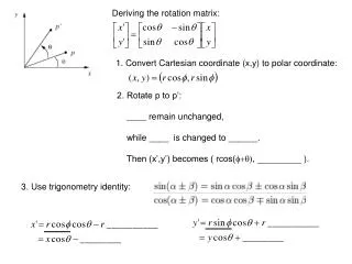
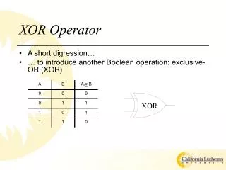
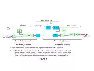
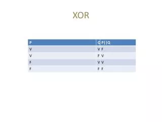
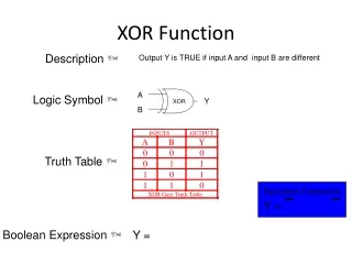
Deriving the XOR Function XOR function can be described verbally as, "Either A or B, but not both." In the realm of digital logic there are several ways of stating this in a more detailed and precise format. We won't go here into such devices as Truth tables and graphic representations. We will stick with the more complete verbal statement, "NOT A and B, or A and NOT B."
Deriving the XOR Function http://www.play-hookey.com/digital/xor_function.html
The Clocked RS NAND Latch • By adding a pair of NAND gates to the input circuits of the RS latch, we accomplish two goals: normal rather than inverted inputs, and a third input common to both gates which we can use to synchronize this circuit with others of its kind
The Clocked RS NAND Latch • http://www.play-hookey.com/digital/clocked_rs_latch.html
The Edge-Triggered RS Flip-Flop • To adjust the clocked RS latch for edge triggering, we must actually combine two identical clocked latch circuits, but have them operate on opposite halves of the clock signal. The resulting circuit is commonly called a flip-flop, because its output can first flip one way and then flop back the other way. The clocked RS latch is also sometimes called a flip-flop, although it is more properly referred to as a latch circuit.
The JK Flip-Flop • http://www.play-hookey.com/digital/jk_nand_flip-flop.html
J-K Flip Flop Timing Diagram
J-K Flip Flop Truth Table Symbol
D Flip Flop J-K input are joined via NOT To make D Flip Flop
Edge-Triggered PGT