Download

1 / 41
410 likes | 594 Vues
Self Balancing Platform A.K.A Magic Plank . Group II Brian Jacobs Kenneth (Rocky) Santiago Jr. Stephen C Fraser II. Motivation. Engineer and implement a unique and challenging, yet feasible senior design project that is distinguishable from other projects. Background (Segway).

E N D
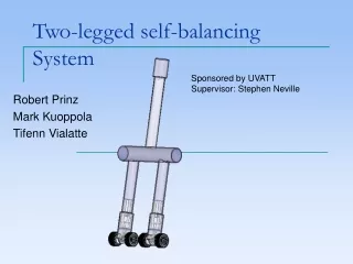
Self Balancing PlatformA.K.AMagic Plank Group II Brian Jacobs Kenneth (Rocky) Santiago Jr. Stephen C Fraser II
Motivation Engineer and implement a unique and challenging, yet feasible senior design project that is distinguishable from other projects.
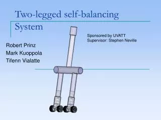
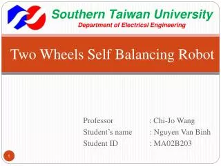
Background (Segway) The Segway personal transportation vehicle, is a two wheeled balancing platform that has seen applications in civilian and military fields.
Background (Project) • Engineer and implement a fully functional two wheeled self balancing platform. • Software governors to maintain max/min speed/acceleration, assisting in maintaining balance. • Explore, engineer, and implement wireless steering.
Background (Continued) Elimination of the steering column sets the Magic Plank apart from a standard Segway. Wheel orientation is altered due to the lack of the steering column, resembling more of a skateboard orientation than that of a Segway. This change shifts the work load of the project heavily towards software.
Outline • Hardware Specifications • Microcontroller • Motor Controller • Bluetooth Device • Inertial Measurement Unit • PCB • Motors & Wheels • Power Supply • Software Design • Software Architecture • Class Diagrams • Sabertooth • IMU • Filter • Bluetooth • Wiimote Integration • Balancer • Administrative Information
Atmel ATmega328p Microcontroller • Low power • Variable Performance • 0 – 20 MHZ @ 1.8 – 5.5 V • 1 MIPS / MHZ • Capable of running the Arduino Software Platform
Sabertooth 2x12 Regenerative Dual Motor Driver • A very robust driver,capable of handlinga heavy payload. • Supply power to two DC brushed motors, 12 A nom, 18 A peak. • Thermal Protection • Compatible controls: • PWM • Radio Control • Serial and Packetized Serial
Bluetooth SMD Module RN-42 Mounted onto Bluetooth Mate Silver Includes power regulator Low Power (45 mA) 3.3V operation Delivers up to 3 Mbps data rate for up to 20 meters(60 ft). Bluetooth Technology V2.0 compatible.
SMD Module RN-42 Communication Utilizes UART and USB data communication interfaces. Auto-discovery/pairing requires no software configuration. Embedded Bluetooth stack profiles included: GAP, SDP, RFCOMM, and L2CAP.
Steering Implementation • Nintendo Wii Wireless Controller, AKA Wiimote, mounted on the Nintendo Wii Steering Wheel. • Powered by two AA batteries. • Will behave as a standard steering wheel. • Operated remotely.
Nintendo Wiimote Communicates via a Bluetooth Wireless link Utilizes a Broadcom 2042 controller chip, designed to be used with devices which follow the Bluetooth Human Interface Device (HID) standard Transmits information via HID input packets HID data packets received and interpreted by code running on laptop computer.
Inertial Measurement UnitIMU3000 & ADXL345 6 Axis Inertial Measurement Unit 3.3V operation I2C Communication Small profile
Inertial Measurement UnitIMU3000 • IMU3000 is a 3-axis gyro with programmable ranges: +/- 250 to +/- 2000 deg/sec • Operates ADXL345 via secondary I2C, only 1 I2C bus needed to communicate with microcontroller
Inertial Measurement UnitADXL345 • ADXL345 is a 3-axis accelerometer with programmable ranges: +/- 2 to +/- 16 g • 3.3V operation • I2C Slave to IMU3000
Printed Circuit Board Runs the ATmega328p Pinouts for the IMU3000 and Bluetooth RN-42
24 Volt 250 Watt Electric Motor Type: Brushed DC Rated Speed: 2600-2850 RPM Rated Current: 13.5-13.7 Amp
Chain Drive Wheel Assembly Overall Diameter: 143.5mm Overall Width: 56.3mm Sprocket: #25 chain, 47 tooth Sprocket Offset: 27mm
9 Ah 12 V Power Supply Style: AGM Length: 5-7/8” Width: 2-1/2” Height: 3-3/4” Weight: 7 lbs ( x 2 = 14 lbs ) Will provide estimated 30-45 min. battery life
Software DesignIMU Communication using I2C Fetch Gyro and Accel values stored in the IMU3000 regs Calibrate using data offsets Convert raw data to angular rate (deg/s) and acceleration (g’s)
Software DesignIMU • Accel operates at a 10-bit resolution • Accel configured for +/-2g range (4gs) • Gyro operates at a 16-bit resolution • Gyro configured for +/- 250 deg/s range (500 deg/s)
Software DesignFilter Takes raw values from IMU Filter out accelerometer’s vibrational noise and the gyroscope’s drift Calibrate using data offsets Outputs current angle (or projected angle) using combined accel and gyro data
Software DesignDetermining Angles • R is the accelerometer’s force vector • Accelerometer’s X-Axis • Gyroscope’s X-Axis
Software Design The Complementary Filter • The equations: x = τ / ( τ + dt ) Θ = x * ( θ + g * dt ) + ( 1 – x ) * a • τ = temporal influence of gyro / accel • Larger τ means more gyro input (less vibration artifacts) • Smaller τ means more accelerometer influence (faster drift correction) • dt = time elapsed between readings • a = new acceleration force in g’s • g = new gyro angle rate in deg/s • θ = current (old) calculated angle • Θ = new calculated angle • Filtering is time sensitive • If dt > τ, drift is corrected • If dt < τ, translation is suppressed
Software DesignBluetooth Gets raw data from Bluetooth device Converts raw data into steering commands Handles dead-manswitch and revivecommand
Wiimote Data Reports • The Wii Remote has a number of different data reporting modes. Each of these modes combines certain Core data features with data from external peripherals, and sends it to the host through one of the report IDs, determined by the mode. • A hexadecimal data packet is sent out every time a value of one of the reported features has changed. An example packet: (a1) 30 00 08 (a1): indicates this packet as input from the Wiimote 0x30: shows the data report mode as 0x30, which in this case reports only button input 0x00 and 0x08: show which buttons have been pressed, with this particular combination indicating that the A button is currently being held down.
Wiimote Accelerometer Data • The Wii Remote includes a three-axis linear accelerometer located on the top surface of the circuit board. • Measures accelerations over a range of at least +/- 3g with 10% sensitivity • Data from the accelerometer is sent in a packet utilizing the following format:(a1) 31 BB BB XX YY ZZ • XX, YY, and ZZ are unsigned bytes representing the acceleration in each of the three axis.
Wiimote Interpreter Program written in C# Receives data packets from the Wiimote using the Wiimotelib library. Requests the numerical representation of the status of the Y-axis of the Wiimote and converts it to a number which can be added directly to the motor speed. Also receives button status which can be interpreted as a command to kill or revive the motors.
Software Dead-Man Switch Controlled by the Wiimote Implemented to ensure the safety of its operators and bystanders The B button located on the back of the Wiimote must be held down at all times in order to keep the Magic Plank in motion The moment the button is released, the Plank terminates operation of the motors until an additional command is received (sent by holding down the B button and pressing the 2 button) which will revive the Magic Plank and resume functionality.
Software DesignBalancer Manages Filter, Sabertooth, and Bluetooth classes Balances platform using PID control Offsets balance with turning data from Bluetooth, moves motors while maintaining equilibrium
Software DesignPID Control PID : Proportional Integral Derivative Control P = Directly proportional to the current angle I = Integral of the angle as a function of time (prevent over-correction) D = Derivative, the change in time (accounts for rapid change) Kp,Ki,Kd = Constants that weight the influence of P, I, and D
Software DesignBalancer • where is the rate of change from the Gyro (deg/s)
Software DesignBalancer Once the Level is determined, steer commands are integrated into the motor commands Offsetting the values allows for the platform to maintain balancing equilibrium