Download
1 / 14
140 likes | 283 Vues
P10203 LV1 motor controller Final Review May 14, 2010. Electrical: Kory Williams, Adam Gillon , Oladipo Tokunboh Mechanical: Louis Shogry , Andrew Krall. Agenda. Project Overview Customer Needs Design Specifications Project Status Schedule Budget Testing Results Issues and Findings

E N D
P10203 LV1 motor controllerFinal ReviewMay 14, 2010 Electrical: Kory Williams, Adam Gillon, OladipoTokunboh Mechanical: Louis Shogry, Andrew Krall
Agenda • Project Overview • Customer Needs • Design Specifications • Project Status • Schedule • Budget • Testing Results • Issues and Findings • Conclusions and Future Work
Project Overview • The purpose of the LV1 motor controller project was to reduce the cost of the previous generation RP1 motor controller while also improving size, manufacturability and appearance. • Our team was to work closely with the other coincident LV1 projects (P10201, P10202, P10205) to create a functional robotic land vehicle with the capability to transport a 1 kg payload.
Customer Needs • The controller is easy to manufacture and assemble. • The controller is modular, (can be configured in several different options to support varied functionality). • The controller has a low risk implementation and is stand-alone. • The controller is able to properly interface with the other modules of the Land Vehicle Platform. • The controller is able to be used by first year mechanical/electrical engineering students. • The controller is able to make the platform move with sufficient agility and controllability. • The new design shall improve upon the aesthetics of the RP1. • The controller makes effective use of the space provided by the Chassis. • The new design is cost effective, (cheaper than the RP1 with the same, or improved performance characteristics). • The controller is durable and can withstand repeated use with minimal maintenance. • The controller has a reasonable battery life. • The controller is able to be upgraded by future Senior Design teams with little redesign or component replacement needed. • The controller makes use of Prior Generations Designs and Research.
Product Development Process • Phase 0: Planning • Define Project Goal • Develop Customer Requirements • Define Engineering Metrics • Phase 1: Concept Selection • 2 Rounds of PUGH Concept Selection • Analysis of existing RP1 • Phase 2: Product Design • Pspice Simulations • Validation using engineering calculations • Phase 3: Final Design • Detailed Schematics and Layout • Finalized BOM • Phase 4: Building • Order parts • Assembly and mounting • Phase 5: Testing • Subsystem • Interfacing MSD1 MSD 2 0 2 4 1 3 5 Current State
Project Status • Controller is able to function independently of the other modules on the LV1 platform. • Controller is able to communicate over the Wireless communications link with the GUI. • Controller is able to drive all four motors at the same time (unmounted) • Battery is compatible with regulation circuits on the controller.
Schedule • Interface testing with Wireless team completed on schedule. • Interface testing with Chassis and Motor Modules fell behind 2 weeks. • Full System testing is still incomplete. Final tests will be run when the platform can be run on the ground.
Budget • Total Cost of Two Controller Units is $798.00 including shipping for parts and components. (20% reduction from the RP1). • Total cost does not include encoder cables that were purchased late due to a miscommunication with the motor module team. • Some components like the mounting plate for the PID controller can be removed from BOM since they were not used.
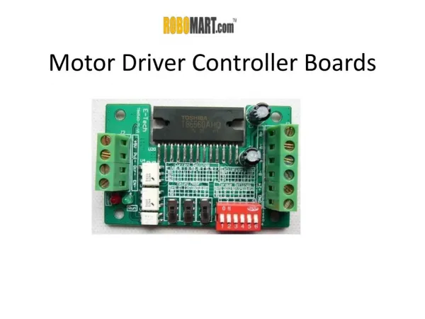
Testing Results • Subsystem Testing • Voltage Regulator boards are functional and able to limit an 8.4V input to 5V (Logic) and 5.93V (Servo). • Motor Driver boards are able to amplify a PWM input signal and provide the stall current condition (1.6A). FWD/REV and speed control are confirmed. • I2C interface between Control Units is confirmed and communications between the devices has been established. • Controller interfaces with the GUI via a wired connection.
Testing Results (cont) • Interface Testing • Communications with the Wireless Team has been established using the GUI to send motor control commands. • Using the GUI, we are able to move the drive motors bidirectionally and with varied speed. Servos are also able to be rotated 180 degrees. • Battery successfully powers up regulator circuits and provides enough voltage to maintain constant Logic and Servo Levels. • Encoder Functionality has not yet been evaluated since motors cannot be driven in contact to the ground.
Issues and Findings • As a subsystem, the controller can operate as intended in the design. • Full System Integration has not yet been established since we are unable to move the robot on the ground. • When the motors try to overcome static friction, there is a large risk of permanent damage to both the drive motor and the motor driver circuitry due to a large current draw. Current limiting circuits may be required in order to obtain proper control of the platform.
Conclusions and Future Work • There are some additional layout issues that can be resolved to make external connections easier. • The thermal coating considerations were dropped due to time restrictions and limited resources. • Additional software knowledge is required for alteration of GUI or program of MCU Unit and PID Controller. • Linear Regulators could be replaced with switching regulators to reduce power loss.