Download
1 / 66
660 likes | 779 Vues
S.M.A.R.T. (Salient Method for Automated Remote Technology) offers an innovative home automation system that integrates lighting control, music playback, and power management into a single user-friendly device. By predicting users' needs and tracking power usage across appliances, S.M.A.R.T. simplifies home management and enhances convenience. Unlike competitors, S.M.A.R.T. goes beyond status reading with its intuitive automation features. The system also aids in locating lost remotes and minimizes time spent on manual playlist creation, offering a smarter living experience.

E N D
S.M.A.R.T.(SALIENT METHOD for AUTOMATED REMOTE TECHNOLOGY) JARRETT GARDNER PADMAVALLI VADALI POOJA SHAH ABHISHEK GAUR
The Plan – Home Automation • Lighting control • Music Playback • S.M.A.R.T. Remote • Power management • Predict the user’s needs • Multi-hop wireless signal
Why S.M.A.R.T. • Control music and home appliances from one easily useable device • Excessive amount of time creating individual playlists • Let something else do your thinking for you • Know your actual power usage for each appliance • Be able to find your lost remote • Competitors • Eaton – can only read the status of a device • X10 & Insteon – extensive product line without behavioral recording or suggestive use
Processor: Atmega8 Board Custom Board Architecture 8 bit micro Von Neumann Arch. 16 MIPS @ 16 MHz 8 KB Prog. Flash 1 KB SRAM 3 Timers 2 8 bit 1 16 bit 10bit ADC 8 channels USART,TWI,SPI 23 I/O Lines Vin: 2.7-5.5 Volts Light Module - Hardware
Light Module – Hardware (digital) • Digital • Power: • ¼ Watts • Input Voltage: 10-36Vdc • DC-DC efficiency: 82% • Clock Rates • Xtal: 8 MHz • A/D clock: 10 kHz • 166 samples per 60Hz cycle
Light Module – Hardware (mains) • “Mains” Power • Vin: 120 V @ 60Hz • Max Current: 6 amps • Fuse: 4 amps • Load • Light Bulb: 40W-300W • Load State: On/Off • 100-0% Power in 10% increments
Light Module - Software • Timers • Timer0 (8bit) • Clock:31.3kHz • Controls triac “on” time ~96 micro seconds • Timer2 (8bit) • Clock: 7.8kHz • Delays triac fire from zero crossing ~0-8msec delay • Temperature • 8 bit reading ever 6 seconds • Convert 10bit hex Celsius reading to ASCII Farenheit • Power • Sample current sensor 10k sps • Calculate power and the average power over 15 minutes • Detect zero crossing of mains • uC must be able to process current every 100us • Lighting control via remote • Dimmer (100%-0% in increments of 10%) • On/Off
Light Module – Software • UART • TX via uart buffer • dynamic buffer • Interrupt driven • RX • Data packet • 0x01 start of packet • 0x02 end of packet • Remote requests current temperature via • 0x01 0x03 0x2D 0x02 • Packet start|Module ID|Command|Packet End
Light Module – Testing 1A • Starting from PCB • Check short between Vcc and ground • Solder uC and attempt to program • Solder DC-DC and test voltages • Solder max232 and DB-9 and test uart • Solder Mains Components • Test for short between hot and neutral • Test for short between hot and load • Test for connections between mains and digital side
Light Module – Testing 1B • Test Traic ON/OFF • Initially fails to turn short hot and load line • Reconfigured with triac driver
Light Module – Testing 2 • Test timer lengths in simulator and actual via oscilloscope
Every Zero Detection True Zero Detection Triac fires at wrong time Light Module – Testing 3
Triac doesn’t always turn off at zero crossing Corrected code for TRIAC fire Removed filtering on triac input Result: now triac doesn’t always turn on Light Module – Testing 5
Processor: Atmega128 Board Custom Board Architecture 8 bit micro Von Neumann Arch. 16 MIPS at 16 Mhz 128K prog. Flash 4 Kbytes SRAM 64K Bytes External Memory JTAG, SPI, TWI Architecture Cont. 4 Timers 8 channel 10 bit ADC Dual Usarts 53 I/O ports Vin 2.7-5.5 Volts Remote - Hardware
Digital Power: Full Power: 1.6 Watts LCD Off: ¼ Watt Input Voltage: 6-18V Controllable regulator to turn LCD ON/OFF Clock Rates Xtal: 8 MHz A/D clock: 62.5 kHz Memory Internal 4KB External 128KB User Control 1 slider 6 capacitive buttons 1 proximity sensor 4 tactile buttons LCD 20 chars x 4 lines Backlight Temperature 10mV/degrees C -55 to 150C Remote – Hardware
Remote - Software • Xtal: 8 MHz • Timers • Timer1 (8bit) • Clock:7.8kHz • Reserved for Testing • Timer2 (8bit) • Clock: 31 kHz • Provides 40usec to 1.5 msec delay for writing to LCD • Timer3 (8bit) • Clock: 7.8kHz • Provides .5 second delay on screen refresh and processing of menu commands • ADC • Clock: 62.5 kHz • Temperature and Power: 1,250 sps • Temperature: converted to Fahrenheit (hex) converted to ascii in menu creation • Power: converted to Volts (hex) converted to ascii in menu creation
Remote – Software • UART Raven • TX via uart buffer • dynamic buffer • Interrupt driven • RX • Process Commands on full reception of packet • Transmission Error: • Next command lost • Restarts at end of next packet (0x02 – packet end) • Uart Debug • TX and RX by polling • Used for Testing purpose only
Remote – Testing 1 • Starting from PCB • Check short between Vcc and ground • Test after soldering every main component • Solder uC and attempt to program • Solder DC-DC and test voltages • Solder max232 and DB-9 and test uart • Solder LCD & Voltage Regulator • Initially blow first pin controlling LCD power • Switched to alternative pin • Check pin connectivity • Make cursor blink • Write commands via uart
Remote – Testing 2 • Solder NVRAM • Check pin connectivity • Write and read value at random address • Write and read external RAM via UART • Solder QPROX • Check pin connectivity • Observe Change line while touching buttons • QPROX fails – incorrect pin layout
Remote – Testing 3 • Solder Tactile Buttons • Short between Vcc and ground, changed orientation • Tested interrupts on button lines • No bouncing problems
Software Tests: UART LCD NVRAM QPROX Buttons Coding LCD LCD Menus Building dynamic content for LCD Commands RX Commands TX Temperature Readings Power Readings Song information transfer from computer to remote Clearing music from memory Refreshing music Remote – Testing 4
Computer Interface - Hardware • Processor: • ATMEL86RF230 • ATMEGA3290PV • ATMEGA1284PV • Board: • AVR Raven • Other Components: • Computer • Costs: • Raven Board $50
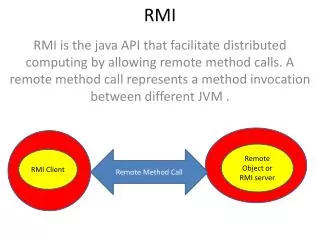
Computer Interface - Software • Python • Packages: • time, threading, serial, string, sys, binascii, os, subprocess,winamp,mutagen • RS232 Polling • Python code executes on complete packet • Song information gathered by mutagen • Play, pause, stop, next track, previous track, create & delete playlists and change volume via winamp package • Activate/disable locator beeper on remote
Computer - Testing • Tested collecting of song information • Connected two serial ports of the computer together via null modem • Tested transmission of new songs • Tested transmission of a title’s crc • Tested all commands on function list