Download
1 / 40
460 likes | 875 Vues
HYDROGEN GENERATORS FOR METEOROLOGY AND INDUSTRY. HYDROGEN GENERATOR TYPE GIP™ 3. Independent Chemical process very easily used Gas reserve possible Especially adapted to isolated areas Reliable. DESCRIPTION. Chemical hydrogen generator GIP ™ 3. Set of accessories :

E N D
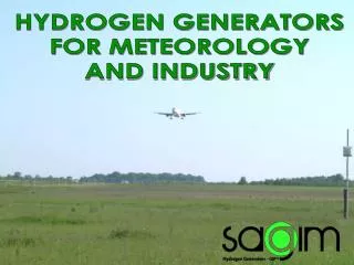
HYDROGEN GENERATORS FOR METEOROLOGY AND INDUSTRY
HYDROGEN GENERATORTYPE GIP™ 3 • Independent • Chemical process very easily used • Gas reserve possible • Especially adapted to isolated areas • Reliable
DESCRIPTION Chemical hydrogen generator GIP™ 3 • Set of accessories: • 1 bucket13 litres • 1 Straight funnel • 1 bent funnel • 1 silicon basket3 m3 • 1 shovel • 1 poker • 1 brass brush • 1 spanner12” • 1 neoprene protective gloves • 1 protective goggle • 1 earthing device Closing assembly And draw off valve
OPERATING PRINCIPLE • The process of hydrogen production with the GIP™ 3 generators is based on the attack of silicon by the caustic soda in aqueous solution under pressure and high temperature. • Its production per cartridge is 3 m3 of hydrogen (measured in conditions at 15 °C and 760 mm of mercury). • The caustic soda undergoes the action of pure silicon in autoclave. • Pressure is produced by the reaction itself, which is not reversible. • A local rise in temperature enables the liquid to reach a temperature high enough to compensate fully the retarding action of the pressure and to insure that the pure silicon is completely attacked. • The hydrogen is stored into the cylinder at high pressure. Chemicalhydrogengenerator type GIP™ 3
TECHNICAL SPECIFICATIONS Chemicalhydrogengenerator type GIP™ 3
GIP™ REACTIVE CARTRIDGE • The GIP™ 3 type hydrogen generator cartridges are stored in waterproof metal boxes made of quantitative dosage of: • alkaline cartridge, • priming cartridge, • granulated silicon cartridge. • A manipulation allows the generation of 3 Nm3 of hydrogen volume within 30 minutes.
GIP™ REACTIVE CARTRIDGES COMPOSITION • 1 GIP™ alkaline cartridge • 1 GIP™ priming cartridge • 1 GIP™ silicon cartridge IDENTIFICATION • GIP™ alkaline cartridge Eutectic mixture of caustic soda and caustic potash • GIP™ priming cartridge Pure silicon powder form • GIP™ silicon cartridge Pure silicon grain form • Customs tariffs 28 15 11 00 00 00 J + 28 04 69 00 00 00 W • NATO Code 36 55 14 507 39 70
MAINS ADVANTAGES • 3 m3 of hydrogen produced in less than 10 minutes • No electricity required • No specific quality of water required • Very few solid residues after the reaction • Low and easy maintenance • Life time of the cylinder up to 30 years • Equipment in accordance with the European regulations in force
ELECTROLYZER TYPE BP-MP Independent Noiseless Automatic Safe Reliable
H2 GENERATOR TYPE BPMP • The hydrogen and oxygen are produced at atmospheric pressure by one or several electrolysis cell serial connected • Each electrolysis cell is made of one anode electrode (oxygen production), one cathode electrode (hydrogen production) and one diaphragm (separation of oxygen and hydrogen). • The oxygen produced is directly evacuated into the atmosphere. • The hydrogen is stored at 5 millibars in the movable bell of the gasholder which is filled when gas is produced. • When the bell is full, the hydrogen is transferred from the gasholder to a storage tank by means of a hydrogen compressor. • The compressor automatically stops as soon as the gasholder bell is empty. • The compressor automatically re-starts when the gasholder bell is full and then stops; the same operating principle occurs until the complete filling of the storage tank. • The system will restart automatically after the filling of a second balloon in order to maintain full the hydrogen tank. • A water treatment system including a 20-liter demineralized water tank allows to make the periodical electrolyte level in the electrolysis cells.
H2 GENERATOR TYPE BPMP HYDROGEN GENERATOR Hydrogen production flow rate0,1 à 10 m3/h Oxygen production flow rate0,05 à 5 m3/h Electrical consumption ≈ 5,00 KWh/Nm3 H2 Hydrogen purity 99,9 ± 0,1% Oxygen purity99,6 ± 0,3% H2 electrolyser pressure outlet Atmospheric H2 storage pressure 4 to 10 Bar Operating temperature 65 °C H2 outlet gas temperature 40 °C Operating intensity 230 to 900 A. DC Operating voltage 2,3 ± 0,5% V. DC UTILITIES Main power supply 220/400 VAC x 3 Fréquency 50/60 Hz Required power 0,9 to 85 kVA
H2 GENERATOR TYPE BPMP Water treatment unit Customer water supply O2 vent Gas holder Limit switches (4) Discharge solenoid valve H2 Pressure switch H2 Mist eliminator H2 vent To H2 storage rectifier Non return valve 3 Electrolyser Compressor Surge tanks & Hydraulic valves
H2 GENERATOR TYPE BPMP ELECTROLYSIS CELL Hydrogen outlet Oxygen outlet Demineralised Water filling Anode Hydrogen compartment Oxygen compartment Cathode Electrolyte level Electroliytic solution Diaphragm Electrolyte drain
ADVANTAGES • Instantaneous starting of the production • Modulation of the production from 0 to 100% • Starting / shutdown entirely static and automatic • Automatic restart of the unit in case of mains opening even prolonged • System control entirely electronic • Operation 24 hours/day continuously • On-line hydrogen analysis, slave to the system • Skid-frame mounting offering:- low space requirement- quick and easy installation • Reduced and easy maintenance • Electrolysis cells lifetime of 20 years • Equipments in accordance with the regulations in force
H2 GENERATOR TYPE MP8 • Instantaneoushydrogen production • Starting of stop sequencesfullystatic and automatic • Pressurizedhydrogen production withoutany compression system • Modulation of the H2 production from 0 to 100% • Operation 24 hours per day and continuously • Automaticgasesdepressurization in case of mains openingshigherthan 30 minutes • Automaticrestarting of the unit in case of mains openingevenprolunged • On-line analizer slave to the system • Automaticfillingcellswith demineralised water • Low and easy maintenance • Easy system for electrolysiscellhandling • Electrolysiscellslifetime 20 years • Buzzeralarm for signalisation • Explosion proof and tropicalised • Equipment in fullycompliancewith the rules in force H2 generator type MP8
H2 GENERATOR TYPE MP8 • The hydrogen and oxygen are produced at atmospheric pressure directly under pressure by two electrolysis cells serial connected. • The electrolysis cell is made of one anode electrode (oxygen production), one cathode electrode (hydrogen production) and one diaphragm (separation of oxygen and hydrogen). • The hydrogen and oxygen produced are directly steered to a pressure balancer. • The pressure balancer has 4 level control probes, each of them having a role: • Safety by oxygen overpressure sign of leak in the hydrogen circuit • Safety by hydrogen overpressure sign of leak in the oxygen circuit • Oxygen / hydrogen pressure relief necessary for the automatic recovery of the electrolyte levels inside the cells • Level control cyclic extraction of the oxygen into the atmosphere • The hydrogen produced is directly transferred towards the storage tank through a weir and a sized hole allowing a flexible and homogenous filling. • The equipment automatically starts again after the filling of a second balloon so as to fill again the storage tank. • The periodical electrolyte level in the cells is automatically restored by adjunction of demineralized water. H2 generator type MP 8
H2 GENERATOR TYPE MP8 HYDROGEN GENERATOR Hydrogen production flow rate0,5 m3/h Oxygen production flow rate0,25 m3/h Electrical consumption ≈ 5,00 KWh/Nm3 H2 Hydrogen purity 99,9 ± 0,1% Oxygen purity99,6 ± 0,3% Electrolyser outlet pressure 0 à 8 Bar Storage pressure 8 Bar Operating temperature 65 °C Outlet gases temperature 40 °C Operating intensity 580 A. DC Operating voltage 2,5 ± 0,5% V. DC UTILITIES Main power supply 220/400 VAC / x 3 Fréquency 50/60 Hz Required power 5,5 kVa H2 generator type MP 8
OPERATING BLOCK DIAGRAM H2 draw-off 5 6 Potable water Eau potable Oxygen vent 5 7 Évent oxygène Hydrogène Oxygène H2 6 1 – Electrolysis cell 2 – Gas balancer 3 – H2 particles filter 4 – O2 particles filter 5 – H2 storage 6 – Gas analyzer 7 – Water treatment unit Vers stockage H2 7 Égout 1 Égout 3 4 2
ELECTROLYSIS CELL 2 Demineralized water inlet 4 O2 outlet 1 3 H2 outlet 1 - Anode 2 - Cathode 3 - Diaphragm asbestos-free 4 – Cooling vane
ADVANTAGES • Instantaneous starting of the production • Modulation of the production from 0 to 100% • Starting / shutdown entirely static and automatic • Automatic restart of the unit in case of mains opening even prolonged • System control entirely electronic • Operation 24 hours/day continuously • On-line hydrogen analysis, slave to the system • Skid-frame mounting offering:- low space requirement- quick and easy installation • Reduced and easy maintenance • Electrolysis cells lifetime of 20 years • Equipments in accordance with the regulations in force
OTHER PRODUCTS ON DEMAND High pressure hydrogen Compression station Hydrogen plant for industry Gas analysis station
OPTIONS - EXTENSIONS PURIFYING AND DRYING UNIT HIGH PRESSURE HYDROGEN STORAGE
SAGIM R&D history • 2003 SOLAR HYDROGEN GENERATOR PROTOTYPE • 2005-2006 CETH (FRANCE) • 2006-2007 FRAUNHOFER INSTITUTE (GERMANY)
SOLAR HYDROGEN GENERATOR PROTOTYPE SOLAR PANELS DC / DC CONVERTER ELECTROLYSER REGULATOR HYDROGEN STORAGE ' BATTERY BACK UP INVERTER SPEED VARIATOR COMPRESSOR
SAGIM SPECIFICATIONS PEM SUPPLIER RESEARCH CETH FRAUNHOFER INSTITUTE PLASTIC STACK DESIGN H2 ELECTROLYSER PROTOTYPE READY TO OPERATE PEM STACK ELECTROLYSERS RANGE Partnership Development of an electrolyser for meteorology Partnership Purchase of a CETH electrolyser Partnership Purchase of a PEM electrolyser Reliability tests Marketing OUR APPROACH TO THE PEM TECHNOLOGY
SAGIM TECHNICAL SPECIFICATIONS • PEM SPECIFICATIONS FOR METEOROLOGY : • H2 production • Output pressure • Gas Purity • Dew point • Power supply • Power Input • Water consumption • Operating temperature • Lifetime of the stack • Easy front panel control and adjustable production from 0% to 100% • Instantanneous starting production and automatic restarting in case of power failure • Water purification system incorporated • at least 0,5Nm3/hour • 4 to 30 Bar • 99,99% (4.0) • 65°C or 10 ppm of H2O • 230/380VAC, 50Hz ±10% • 4 to 5Kwh/Nm3 • 1L/Nm3 • 0 to 70°C • 10 000 hours (5 years, 6h per day)
CETH PEM MODULE TECHNICAL DATA : H2 Production rate 0,1 to 2Nm³/h Hydrogen quality 99,99% Impurities after purification O2 in H2 < 10 ppm H2O in H2 < 10 ppm Power supply 230/380 VAC, 50Hz, PFC Power input around 4KWh/Nm³ Required water quality Deionized water <1 S Operating pressure 5 to 15 bars 20 to 30 bars with a steel bell Lifetime 10 000 hours continuously CETH STACK 1 Nm³/h under 30 bars
CETH GENHY 1000 ELECTROLYSER TECHNICAL DATA: H2 Production rate 1Nm ³/h Hydrogen quality 99.9% Maximum H2 Temperature 80°C Water consumption around 1 L/Nm³ Power supply 230/380 VAC, 50Hz Power input 5KWh/Nm³ max Required water quality Deionized water <1 S Operating pressure 7 to 30 bars INCONVENIENTS : GENHY 1000 1Nm³/h CETH PEM MODULE: 40 000 euros CETH GENHY 1000 ELECTROLYSER: 100 000 euros
FRAUNHOFER PEM MODULE TECHNICAL DATA: H2 production rate 110 L/h Hydrogen quality 99.98% Number of cells 15 cells Total voltage of the stack 35VDC maximum Required water quality Deionized water <1 S Maximum water temperature 90°C Light weight PEM cell stack with bipolar plates made from plastics
FRAUNHOFER PEM ELECTROLYSER TECHNICAL DATA: H2 Production rate 110 L/h of H2 Hydrogen quality 99.98% Operating temperature Maximum 54°C Power supply 230 VAC, 50Hz, PFC Power input 700 VA Required water quality Deionized water <1 S Max. production amount with 1 Nm ³ one full water tank Operating pressure 8 to 9,5 bars max Overall dimensions 600 x 620 x 500 mm Weight 48 kg Fraunhofer ELECTROLYSER 110 L/h INCONVENIENT : H2 maximum production : 110L/h
RESULTS OF FRAUNHOFER PEM TESTS • Tests of the generator between May and October 2007 • After 400 Hours of functionning : • Stack out of order • Strong corrosion of the H2 side, Ti membrane, electrode • Plates made from plastic OK • Today : • Modifications of the regulation system by Fraunhofer • Replacement of the cells stack by Fraunhofer • Beginning of new reliability tests at the end of january by SAGIM
Prospects : • Utilisation of a phosphate solution to replace alcaline solution • Better electrolysis energy efficiency To Resume : CETH Technology: - Good production range - Generator and stack of cellstooexpensive - No real experience return on the stack - Maximum pressure 30 bars Fraunhofer Technology : - Maximum production toolow (110L/h) - Lifetime of the stacktoo short (400h) - Easy use
FOR MORE INFORMATION PLEASE CONTACT SAGIM S.A. 35, RUE SCHEURER-KESTNER 42000 SAINT-ÉTIENNE (France) Tel. : + 334 77 92 20 00 Fax : + 334 77 74 71 09 contact@sagim-gip.com www.sagim-gip.com THANK YOU