A Subspace Method for MIMO Radar Space-Time Adaptive Processing
A Subspace Method for MIMO Radar Space-Time Adaptive Processing. Chun-Yang Chen and P. P. Vaidyanathan. California Institute of Technology Electrical Engineering/DSP Lab. ICASSP 2007 student paper contest. Outline. Review of the background MIMO radar Space-Time Adaptive Processing (STAP)

A Subspace Method for MIMO Radar Space-Time Adaptive Processing
E N D
Presentation Transcript
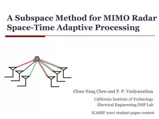
A Subspace Method for MIMO Radar Space-Time Adaptive Processing Chun-Yang Chen and P. P. Vaidyanathan California Institute of Technology Electrical Engineering/DSP Lab ICASSP 2007 student paper contest
Outline • Review of the background • MIMO radar • Space-Time Adaptive Processing (STAP) • The proposed MIMO-STAP method • Formulation of the MIMO-STAP • Prolate spheroidal representation of the clutter signals • Deriving the proposed method • Simulations Chun-Yang Chen, Caltech DSP Lab | ICASSP 2007 student paper contest
The radar systems which emits orthogonal (or noncoherent) waveforms in each transmitting antennas are called MIMO radar. MIMO Radar MIMO radar SIMO radar (Traditional) w2f(t) f2(t) w1f(t) f1(t) w0f(t) f0(t) Chun-Yang Chen, Caltech DSP Lab | ICASSP 2007 student paper contest
The radar systems which emits orthogonal (or noncoherent) waveforms in each transmitting antennas are called MIMO radar. MIMO Radar MIMO radar SIMO radar (Traditional) w2f(t) f2(t) w1f(t) f1(t) w0f(t) f0(t) [D. J. Rabideau and P. Parker, 03] [D. Bliss and K. Forsythe, 03] [E. Fishler et al. 04] [F. C. Robey, 04] [D. R. Fuhrmann and G. S. Antonio, 05] Chun-Yang Chen, Caltech DSP Lab | ICASSP 2007 student paper contest
SIMO Radar (Traditional) Transmitter: M antenna elements Receiver: N antenna elements ej2p(ft-x/l) ej2p(ft-x/l) dT dR w0f(t) w1f(t) w2f(t) Transmitter emits coherent waveforms. Number of received signals: N Chun-Yang Chen, Caltech DSP Lab | ICASSP 2007 student paper contest
MIMO Radar Transmitter: M antenna elements Receiver: N antenna elements ej2p(ft-x/l) ej2p(ft-x/l) dR dT … MF MF f0(t) f2(t) f1(t) … Matched filters extract theMorthogonal waveforms. Overall number of signals: NM Transmitter emits orthogonal waveforms. Chun-Yang Chen, Caltech DSP Lab | ICASSP 2007 student paper contest
MIMO Radar – Virtual Array f2(t) q ej2p(ft-x/l) ej2p(ft-x/l) q q dR dT=NdR … MF MF f0(t) f1(t) … Transmitter: M antenna elements Receiver: Nantenna elements Virtual array: NM elements Chun-Yang Chen, Caltech DSP Lab | ICASSP 2007 student paper contest
MIMO Radar – Virtual Array (2) [D. W. Bliss and K. W. Forsythe, 03] + = Virtual array: NM elements Transmitter:Melements Receiver: N elements The spatial resolution for clutter is the same as a receiving array with NM physical array elements. NM degrees of freedomcan be created using only N+M physical array elements. Chun-Yang Chen, Caltech DSP Lab | ICASSP 2007 student paper contest
Space-Time Adaptive Processing The adaptive techniques for processing the data from airborne antenna arrays are called space-time adaptive processing (STAP). airborne radar v vsinqi qi jammer target vt i-th clutter Chun-Yang Chen, Caltech DSP Lab | ICASSP 2007 student paper contest
Space-Time Adaptive Processing The adaptive techniques for processing the data from airborne antenna arrays are called space-time adaptive processing (STAP). airborne radar v vsinqi The clutter Doppler frequencies depend on angles. So, the problem is non-separable in space-time. qi jammer target vt i-th clutter Chun-Yang Chen, Caltech DSP Lab | ICASSP 2007 student paper contest
Space-Time Adaptive Processing (2) L: # of radar pulses Non separable: NLtaps Separable: N+Ltaps Angle processing L Doppler processing Space-time processing Jointlyprocess Doppler frequencies and angles Independentlyprocess Doppler frequencies and angles Chun-Yang Chen, Caltech DSP Lab | ICASSP 2007 student paper contest
+ MIMO Radar STAP MIMO Radar STAP NM signals NL signals M waveforms MIMO STAP [D. Bliss and K. Forsythe 03] N: # of receiving antennas M: # of transmitting antennas L: # of pulses NML signals Chun-Yang Chen, Caltech DSP Lab | ICASSP 2007 student paper contest
MIMO Radar STAP (2) MVDR (Capon) beamformer: NML signals Chun-Yang Chen, Caltech DSP Lab | ICASSP 2007 student paper contest
MIMO Radar STAP (2) Pros MVDR (Capon) beamformer: NMLxNML NML signals Cons Very good spatial resolution High complexity Slow convergence Chun-Yang Chen, Caltech DSP Lab | ICASSP 2007 student paper contest
We first observe each of the matrices Rc and RJ has some special structures. We show how to exploit the structures of these matrices to compute R-1more accurately and efficiently. The Proposed Method clutter jammer noise Chun-Yang Chen, Caltech DSP Lab | ICASSP 2007 student paper contest
Formulation of the Clutter Signals Clutter points … n-th antenna m-th matched filter output l-th radar pulse Matchedfilters Matchedfilters Matchedfilters Pulse 2 c112 c202 c212 c002 c012 c102 • Nc: # of clutter points • ri: ith clutter signal amplitude Pulse 1 c111 c201 c211 c001 c011 c101 c110 c200 c210 c000 c010 c100 Pulse 0 cnml: clutter signals Chun-Yang Chen, Caltech DSP Lab | ICASSP 2007 student paper contest
Simplification of the Clutter Expression Chun-Yang Chen, Caltech DSP Lab | ICASSP 2007 student paper contest
Simplification of the Clutter Expression Re{c(x;fs,i)} Re{c(n+gm+bl;fs,i)} 1.5 1 0.5 0 -0.5 -1 -1.5 -2 0 2 4 6 8 10 12 x Chun-Yang Chen, Caltech DSP Lab | ICASSP 2007 student paper contest
“Time-and-Band” Limited Signals The signals are well-localized in a time-frequency region. Time domain [0 X] To concisely represent these signals, we can use a basis which concentrates most of its energy in this time-frequency region. Freq. domain [-0.5 0.5] Chun-Yang Chen, Caltech DSP Lab | ICASSP 2007 student paper contest
Prolate Spheroidal Wave Functions (PSWF) is called PSWF. 0 X -0.5 0.5 in [0,X] Frequency window Time window Chun-Yang Chen, Caltech DSP Lab | ICASSP 2007 student paper contest
Prolate Spheroidal Wave Functions (PSWF) is called PSWF. 0 X -0.5 0.5 in [0,X] Frequency window Time window [D. Slepian, 62] Only X+1 basis functions are required to well represent the “time-and-band limited” signal Chun-Yang Chen, Caltech DSP Lab | ICASSP 2007 student paper contest
Clutter Representation by PSWF consists of NML N+g(M-1)+b(L-1) Chun-Yang Chen, Caltech DSP Lab | ICASSP 2007 student paper contest
Clutter Representation by PSWF consists of NML N+g(M-1)+b(L-1) can be obtained by sampling from . The PSWF can be computed off-line Chun-Yang Chen, Caltech DSP Lab | ICASSP 2007 student paper contest
Clutter Representation by PSWF consists of NML N+g(M-1)+b(L-1) can be obtained by sampling from . The PSWF can be computed off-line The NMLxNML clutter covariance matrix has only N+g(M-1)+b(L-1) significant eigenvalues. This is the MIMO extension of Brennan’s rule (1994). Chun-Yang Chen, Caltech DSP Lab | ICASSP 2007 student paper contest
Jammer Covariance Matrix jammer Matchedfilters Matchedfilters Matchedfilters Pulse 2 j112 j202 j212 j002 j012 j102 Pulse 1 j111 j201 j211 j001 j011 j101 j110 j200 j210 j000 j010 j100 Pulse 0 jnml: jammer signals Chun-Yang Chen, Caltech DSP Lab | ICASSP 2007 student paper contest
Jammer Covariance Matrix jammer Jammer signals in different pulses are independent. Matchedfilters Matchedfilters Matchedfilters Pulse 2 j112 j202 j212 j002 j012 j102 Pulse 1 j111 j201 j211 j001 j011 j101 j110 j200 j210 j000 j010 j100 Pulse 0 jnml: jammer signals Chun-Yang Chen, Caltech DSP Lab | ICASSP 2007 student paper contest
Jammer Covariance Matrix jammer Jammer signals in different pulses are independent. Jammer signals in different matched filter outputs are independent. Matchedfilters Matchedfilters Matchedfilters Pulse 2 j112 j202 j212 j002 j012 j102 Pulse 1 j111 j201 j211 j001 j011 j101 j110 j200 j210 j000 j010 j100 Pulse 0 jnml: jammer signals Chun-Yang Chen, Caltech DSP Lab | ICASSP 2007 student paper contest
Jammer Covariance Matrix jammer Jammer signals in different pulses are independent. Jammer signals in different matched filter outputs are independent. Matchedfilters Matchedfilters Matchedfilters Pulse 2 j112 j202 j212 j002 j012 j102 Pulse 1 j111 j201 j211 j001 j011 j101 j110 j200 j210 j000 j010 j100 Pulse 0 jnml: jammer signals Block diagonal Chun-Yang Chen, Caltech DSP Lab | ICASSP 2007 student paper contest
The Proposed Method low rank block diagonal Chun-Yang Chen, Caltech DSP Lab | ICASSP 2007 student paper contest
The Proposed Method low rank block diagonal By Matrix Inversion Lemma Chun-Yang Chen, Caltech DSP Lab | ICASSP 2007 student paper contest
The Proposed Method low rank block diagonal By Matrix Inversion Lemma • The proposed method • Compute Yby sampling the prolate spheroidal wave functions. Chun-Yang Chen, Caltech DSP Lab | ICASSP 2007 student paper contest
The Proposed Method low rank block diagonal By Matrix Inversion Lemma • The proposed method • Compute Yby sampling the prolate spheroidal wave functions. • Instead of estimating R, we estimate Rv and Rx. The matrix Rv can be estimated using a small number of clutter free samples. Chun-Yang Chen, Caltech DSP Lab | ICASSP 2007 student paper contest
The Proposed Method low rank block diagonal By Matrix Inversion Lemma • The proposed method • Compute Yby sampling the prolate spheroidal wave functions. • Instead of estimating R, we estimate Rv and Rx. The matrix Rv can be estimated using a small number of clutter free samples. • Use the above equation to compute R-1. Chun-Yang Chen, Caltech DSP Lab | ICASSP 2007 student paper contest
The Proposed Method – Advantages Inversions are easy to compute :block diagonal :small size Chun-Yang Chen, Caltech DSP Lab | ICASSP 2007 student paper contest
The Proposed Method – Advantages Low complexity Inversions are easy to compute :block diagonal :small size Chun-Yang Chen, Caltech DSP Lab | ICASSP 2007 student paper contest
The Proposed Method – Advantages Low complexity Inversions are easy to compute :block diagonal :small size Fewer parameters need to be estimated Chun-Yang Chen, Caltech DSP Lab | ICASSP 2007 student paper contest
The Proposed Method – Advantages Low complexity Inversions are easy to compute :block diagonal :small size Fast convergence Fewer parameters need to be estimated Chun-Yang Chen, Caltech DSP Lab | ICASSP 2007 student paper contest
The Proposed Method – Complexity Complexity: Chun-Yang Chen, Caltech DSP Lab | ICASSP 2007 student paper contest
The Zero-Forcing Method • Typically we can assume that the clutter is very strong and all eigenvalues of Rx are very large. Chun-Yang Chen, Caltech DSP Lab | ICASSP 2007 student paper contest
The Zero-Forcing Method • Typically we can assume that the clutter is very strong and all eigenvalues of Rx are very large. • Zero-forcing method • The entire clutter space is nulled out without estimation Chun-Yang Chen, Caltech DSP Lab | ICASSP 2007 student paper contest
Simulations Parameters: N=10, M=5, L=16 CNR=50dB 2 jammers, JNR=40dB SINR of a target at angle zero and Doppler frequencies [-0.5, 0.5] 0 MVDR known R (unrealizable) -2 Sample matrix inversion K=1000 -4 Diagonal loading K=300 -6 Principal component K=300 SINR (dB) -8 Proposed method K=300,Kv=20 -10 Proposed ZF method Kv=20 -12 -14 K: number of samples Kv: number of clutter free samples collected in passive mode -16 -0.5 -0.4 -0.3 -0.2 -0.1 0 0.1 0.2 0.3 0.4 0.5 Normalized Doppler frequency Chun-Yang Chen, Caltech DSP Lab | ICASSP 2007 student paper contest
Conclusion and Future Work • Conclusion • The clutter subspace is derived using the geometry of the problem.(data independent) • A new STAP method for MIMO radar is developed. • The new method is both efficientandaccurate. • Future work • This method is entirely based on the ideal model. • Find algorithms which arerobust against model mismatch. • Develop clutter subspace estimation methods using a combination of both the geometryandthereceived data. Chun-Yang Chen, Caltech DSP Lab | ICASSP 2007 student paper contest
Thank You! Q&A Any questions? Chun-Yang Chen, Caltech DSP Lab | ICASSP 2007 student paper contest