TROUBLESHOOTING
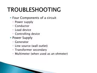
TROUBLESHOOTING. Four Components of a circuit Power supply Conductor Load d evice Controlling device Power Supply Generator Line source (wall outlet) Transformer secondary Multimeter (when used as an ohmeter). TROUBLESHOOTING. Conductors Wires Solder runs (see on circuit board)

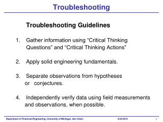
TROUBLESHOOTING
E N D
Presentation Transcript
TROUBLESHOOTING • Four Components of a circuit • Power supply • Conductor • Load device • Controlling device • Power Supply • Generator • Line source (wall outlet) • Transformer secondary • Multimeter (when used as an ohmeter)
TROUBLESHOOTING • Conductors • Wires • Solder runs (see on circuit board) • Circuit protection devices (fuses, circuit breakers) • Load devices • Heating elements • Relay coils • Solenoids • Resistors
TROUBLESHOOTING • Multimeter (when used as a voltmeter) • Motors • Lamps • NOTE: Not All Load Devices Demonstrate Their Use Of Power (Resistors And Transformers) • Controlling devices • Switches • Relay
TROUBLESHOOTING Figure 1. Basic DC Circuit NOTE: S1 is optional
TROUBLESHOOTING • Circuit Simplification • How circuits are identified: • By what mfg or engineer states • By load device • By load device and controlling device (a switch), ie (S3) • By load device and lock-in path • Load device and locked in an energized state by controlling device (relay points) • Lock in path is an alternate path of current • By load device and mode of operation
TROUBLESHOOTING • Developing an operational chart and sequence of events • Mechanical - what the operator does to get the circuit to perform (flip switches, set timer, control settings, etc) • Electrical - what happens electrically in the circuit in response to the operators actions (lamp lights, motor runs, etc) • State of the load device • Load device energized • Load device is not energized
TROUBLESHOOTING • Troubleshooting Procedure • Perform sequence of events • Write down all symptoms - things which you should see, hear, or feel happen but do not • Terminology used to identify symptom • DNE - device fails to energize at any time • DNLI - device energizes but fails to lock in • DNDE - device does not de-energize at designated time
TROUBLESHOOTING • Circuit analysis • Rule out all component(s) which do not cause all symptoms shown • Identify all components which could cause all operational symptoms • Check current path of faulty component(s) for good voltage • Choose a half way point for troubleshooting large circuits
TROUBLESHOOTING • Identifying Possible Malfunctions Using Circuit Extracts • Format for circuit extracts • Rectangular • Power source on left (only) • Load device on right (only) • Conductor on top and bottom to include switches and tie points • Size • Only one per normal size sheet of paper, on both sides • Large enough to read at a glance
TROUBLESHOOTING • Labeling • Must include tie points • All components must be labeled • All switches will be drawn in the position they are shown in on the main schematic • Include all wire colors and wire numbers • Advantage in troubleshooting • Easier to parallel troubleshoot (sides of line easily open) • Concentrates attention on circuit to be troubleshot rather than entire schematic
TROUBLESHOOTING • Use of voltmeter (locating the problem) • Measures the voltage difference between the two leads • Black lead - reference lead - common • Red lead - testing lead • Set meter to read what you would normally expect to find • Voltmeter compares the voltage on the red lead to the voltage on the black lead
TROUBLESHOOTING • A voltmeter is like a loaddevice • When the meter indicates a voltage level all conductors between the power source and meter leads must be good NOTE: Start meter at highest setting for safety and about ghost voltage • If the meter does not read a voltage and power is applied, there is an open between the power source and the meter leads NOTE: A multimeter set to ohms works differently - the meter is the power source and it checks the resistance to current flow between the meter leads
TROUBLESHOOTING • Determine reference point • Know a good point in functioning area of circuit • If entire unit does not work place leads across incoming power - if meter reads voltage, leave one lead in place for reference • When moving into a different power supply you must move your reference lead to within the power supply to be tested
TROUBLESHOOTING • Parallel Troubleshooting • NOTE: Before ANY type of troubleshooting takes place, all switches and or controlling devices MUST be in the proper position as to energize the load device • The most common method involves keeping meter parallel to power source and load device - one lead on each side of incoming power line
TROUBLESHOOTING • Procedure • Connect reference lead • Check other side of line with testing lead • Start at first known point closest to power source • Check point by point out to load device • If voltage read up to load device - that side of the line is good as a reference and then check the other side of the line up to the load device • If the meter reading is 0 volts the open is between the last place you read voltage and the first place 0 volts was read • If voltage is read to both sides of a load device and it does not energize - LOAD DEVICE IS OPEN • When the meter indicates a voltage level it is energized
TROUBLESHOOTING Figure 3. Basic DC Circuit 2
TROUBLESHOOTING • Series Troubleshooting • Keeps leads on the same incoming line • Zero voltage means that the line between the two test leads are good • Applied voltage read on a meter means there is an open somewhere between the two testing leads • Procedure • Determine which line you will check first and connect the reference lead as close to the power source as possible
TROUBLESHOOTING • Insure that the reference is good by checking the opposite line for applied voltage • Check point by point out to the load device until applied voltage is found • If applied voltage is found; then the open is between where the voltage was found and the last reading of zero volts • If zero volts is found up to the load device, then the side of the line you are testing is good and the procedure should be repeated on the opposite side of the line
TROUBLESHOOTING • Loop Troubleshooting Method • Loop troubleshooting is a combination of both series and parallel methods • As with either of the above methods, the object is to locate an open by observing a difference of potential where there should be none • Procedure • Connect the reference lead as close to the incoming power supply as possible (usually the neutral or dc negative side) • Test for incoming voltage at the power supply
TROUBLESHOOTING • Move along the hot line and parallel troubleshoot this line • Once at the load device (if an open hasn't been found already) cross over the load device and troubleshoot in the series method until an open is found • Note: If You Read Applied Voltage On The Top Of The Load DEVICE, AND ZERO volts on the bottom of the load device, and the load device is not energizing the load device itself is open.
TROUBLESHOOTING Figure 4. Basic DC Circuit 3
TROUBLESHOOTING • Use of the Oscilloscope in Fault Isolation • Displays voltage in the form of a signal • Black lead - reference lead - common • Probes - 10x or 1x • Oscilloscope compares the voltage on the probe tip to the voltage on the reference lead and displays it as a signal
TROUBLESHOOTING • An oscilloscope is like a load device • When the oscilloscope displays a proper reading, it is energized • When the oscilloscope displays a proper reading, all conductors between the power source and leads must be good • If the oscilloscope does not displays the proper reading, and power is applied, there is an open between the power source and the leads
TROUBLESHOOTING • Determine reference point • Known good in functioning area of circuit • If entire unit does not work place leads across incoming power - if meter reads voltage, leave one lead in place for reference • Meter Readings • NOTE: It is good practice to determine what voltage readings should be present before meter is placed in the circuit
TROUBLESHOOTING • Opens • An open is a break in the path of current flow • Infinite resistance • No current flow • Drops the applied voltage • If an open is present in a circuit, the circuit will not function
TROUBLESHOOTING Figure 5. Basic DC Circuit 4
TROUBLESHOOTING • Shorts • A short is an abnormal path for current flow • No resistance • Maximum current flow • No voltage drop • Types of shorts • Damaging: will change the resistance of a circuit and may cause fuse(S) to blow • Non-Damaging: will not change the resistance of a circuit • Across a load device (or power supply) - changes the resistance of a circuit and may cause fuse(s) to blow • From one circuit to another - ie, high voltage circuit to a low voltage circuit - may not change circuit operation but could cause a safety hazard
TROUBLESHOOTING Figure 6. Damaging Short Figure 7. Non Damaging Short
TROUBLESHOOTING • Pictures of faults (diagrams) • Show faults between two nearest point • Label all points and wires • Use proper schematic symbols • If fault is a load device - device must be label • State whether the fault is an open or a short
TROUBLESHOOTING • Half-Split Analysis • The use of half-split analysis is fundamental to logical troubleshooting • it is relatively simple • always applicable when troubleshooting an instrument or system which consists of a series of functions Figure 8. Application of Half-split Analysis
TROUBLESHOOTING • When troubleshooting a functional-series circuit, make your first check at the point where the circuit divides (split the circuit in half) • If the desired response is present, the problem is located between the checkpoint and the output and the limits can be moved to encompass this area • If the desired response is not present, the problem is probably located between the input and the checkpoint and again, the limits can be moved to encompass this area
TROUBLESHOOTING Figure 9. Taking the Next Step with Half-split Analysis
TROUBLESHOOTING Figure 10. Localizing the Problem with Half-split Analysis
TROUBLESHOOTING • After we have reduced the limits of the problem to the smallest circuit area, we look at the section of the circuit schematic and make individual resistance, voltage and current checks to determine the particular faulty components • Feedback Analysis • When analyzing a feedback-controlled system or network, break (disconnect) the feedback loop • If the output of the system or network does not change, the problem is in the feedback loop • If the output changes radically, the problem is in the system or the circuit
TROUBLESHOOTING • The first check of the feedback-controlled system is restricted to its output • Consists of measuring it as you disconnect the feedback loop • This measurement might be a voltmeter, or oscilloscope • Always remember feedback is used to control • When you remove affective control, you have rapid and large change • When you remove ineffective control, you have slow and minute change
TROUBLESHOOTING • Conclusions • The expert troubleshooter utilizes all of his or her senses to isolate and eliminate a problem as rapidly as possible • They use the techniques of: • Circuit analysis • Series troubleshooting • Parallel troubleshooting • Loop troubleshooting • Half-split analysis • Feedback analysis
TROUBLESHOOTING • To set initial limits within which his problem is located and the relentlessly reduces those limits until he has reduced the problem to a specific defect • With practice of the techniques detailed here, you can improve your effectiveness and, therefore, your value within the hospital.
TROUBLESHOOTING • NOTE: Four Steps for Success • Know what you expect to see at any given point prior to taking a measurement • Insure your test equipment is set to read / display the proper voltage or signal • Insure that your reference is good by checking the incoming voltage or signal • Insure that all controlling and/or switching devices are in the proper position to energize the load device that you are troubleshooting