Next-Generation SKA Station Design Approach
Discussing project target, work description, partnerships, activities, evaluation results, conclusion, and design specifications for a new SKA station design.

Next-Generation SKA Station Design Approach
E N D
Presentation Transcript
AA-mid demonstrator Dion Kant AAVP 2010 8 – 10 December 2010, Cambridge, UK.
Outline • Project target • Description of Work • Project partnerships • Current activities • Evaluation results • Conclusion
AA-mid (draft) key requirements Requirements may still be adapted
AA-mid time line, phases and • Full project (~2000 m^2 AA) not funded today • AAVS1 = first phase • Funding for design phase within AAVS1 • 2010 to 2013 • Delivers design + small number of front end proto types • Use EMBRACE evaluation as input for design • Use EMBRACE platform as test-bed for new tile developments • New design based on EMBRACE • Site selection will be decided on later • First testing will be performed at current EMBRACE stations • Second stage testing: Use Portugal site (SKA like environment) • Second phase (AAVS2) (beyond 2013) full roll-out AA-mid demonstrator
Design approach • Base new design on EMBRACE architecture and other demonstrators • Incremental approach • Level 1 topics (should) • Level 2 topics (may) • Main enhancements are (level 1 topics): • Introduce dual polarisation signal processing • Reduce power consumption per signal path • Improve tile control system • Reduce system noise • Second generation beam former chip (4-bit phase control) • Improve mechanical design, this includes housing & radome • Improve design for manufacturability
Design approach level 2 topics • Investigate LNA above ground plane (integrated on feed board). Main goal is to be able to use FR4 for feed board (element cost reduction) • Investigate balanced LNA approach • Improve station processing bandwidth • Input bandwidth (250 MHz per channel) • Output bandwidth >2x250 MHz • As a fall back current EMBRACE processing hardware will be used • Investigate non-continues Unit/substation approach; • Obtain better EM model of tile to predict radiation pattern including polarisation behavior. • ….
Non-continues substations • XX “tiles” in a substation. • Every substation slightly tilted. • Substation closed by EPS wall en top. • Passive cooling by ground connection through poles. • SKA station formed by multiple substations. • Walkable spaces between substations. • 56m diameter 288.000 antenna elements 7
Design approach level 2 topics Topics to be solved : • Need software development partnership • Need correlator suitable for 15x2x1GS/s inputs • … Can survive with current EMBRACE system in first phase of the project
Project partnerships • Established members: • OPAR, France: Part of system design, beam former chip design, EMBRACE evaluation; • ASTRON, the Netherlands: Part of system design, focus on level 1 front-end topics, industrialisation and EMBRACE evaluation • … • Members (becoming established): • Italy, INAF: Possible topics: Receiver, LO system, … • UK Several Institutes: Antenna design alternatives including electronic integration and testing, Digital processing, … • Germany, MPIfR: Signal distribution and multiplexing, digital processing; • Portugal, Preparation for Portugal station roll out and site development • France, AD converter including poly phase filter bank integration • …
Octa boards Center board Connection boards Aluminum ground plane Current Activities and Progress • First AAmid proto type tile underway
Current Activities and Progress • First AAmid proto type tile underway Bottom view Octa concept
AAmid Octa Concept; 3D bottom view Current Activities and Progress
Improved element mechanics Multiple vivaldiantennas in one sheet Plastic support to keep tops in place LNA close to pick-up point SKA Station Design
Aluminum Large Plates to decrease assembly time Also expandable (connectable) in other direction Metal-Metal joining by clinching SKA Station Design
EM analysis of non-continues substations • XX “tiles” in a substation. • Every substation slightly tilted. • Substation closed by EPS wall en top. • Passive cooling by ground connection through poles. • SKA station formed by multiple substations. • Walkable spaces between substations. • 56m diameter 288.000 antenna elements 15
EM analysis of non-continues substations Vacuum formed “tile” bottom for six modules (approx. 1.5 x 2m) Placement in field by forklift or crane, like LOFAR HBA.
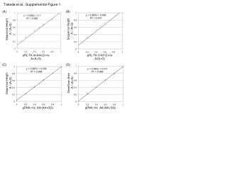
Good resemblance model and measurements Active reflection coefficients 3 = Central 1 = Edge
Good resemblance model and measurements Measured and simulated phases
Current Activities and Progress • EMBRACE Evaluation and test-bed development
Current Activities and Progress Status Nançay Station • ~ 62 m2 area 56 Tiles • 4032 Vivaldi elements (single linear polarisation) • Currently 48 tiles cabled up end-to-end • Grouped into tilesets of 4 tiles • 64 tiles to be installed by end 2010 • Ultimately, 80 tiles in early 2011
Current Activities and Progress Status Westerbork Station • 64 Tiles, (~70 m^2) • 25 Tiles online in a 3x3 and 4x4 array configuration • Ultimately 144 Tiles (160 m^2) in 2011
Modified architecture to more generic one • Full data rate can be exploited: • 2x62 Ebeamlets per CDO output; e.g. two beams of 12 MHz each • Digital beam former software less complex (can use Matrix formalism now) • Increased update rate digital beam weights
Current Activities and Progress EMBRACE station experiment objectives and results • Detection of GPS satellite signals • Scanned Beam Pattern on Afristar • Redundant base line experiments on Afristar • Solar Fringes and system noise verification • Fringes of Cas A and Cygnus • RECENT RESULT: Detection of pulsar Plan • Simultaneous detection of two pulsars within one FoV • Simultaneous detection of two widely separated pulsars using independent FoVs • Detection of HI • Simultaneous detection of HI and pulsars • Beam swapping with beams on Cas A and Cygnus • Correlate with WSRT dish • RECENT RESULT: Detection of pulsar
Drift scan of GPS satellite • Strong carrier at 1227MHz • Subband statistics • Pointing offset between tilesets
Early highlights: solar fringes • Interferometric measurement with 10 tiles • two E-W ULAs • frequency: 1179 MHz • integration: 10 s • bandwidth: 195 kHz • Initial performance est. • A/T = 4.7·10-3 (to sun) • Tsys = 103 – 117 K (to zenith)
Early highlights: instrument quality • Redundant baselines produce redundant visibilities
Scanned Tile Beam pattern measured on Afristar satellite Model Measurement
Fringes of Cas A! • Experimental settings • 3x3 array • 1254 MHz • 30 s integration • 195 kHz bandwidth • Initial conclusions • Confirms A/T • Correlation offsets
Conclusion • AA-mid is ramping up • EMBRACE Pulsar Detection demonstrates first L-band AA detection ever! It demonstrates: • Complete data path and processing is under control • Hierarchical beam forming is working • and much more to come Thank you