Transformer Regulation and Efficiency
350 likes | 740 Vues
Learn about the importance of transformer rating in kVA, why regulation is crucial, types of losses in transformers, calculation of efficiency, conditions for maximum efficiency, and the concept of all-day efficiency. Explore practical examples for better understanding.

Transformer Regulation and Efficiency
E N D
Presentation Transcript
Lecture on Transformer Regulation www.AssignmentPoint.com www.assignmentpoint.com
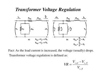
Why Transformer Rating in kVA? As seen, Cu loss of transformer depends on current and iron loss on voltage. Hence, total transformer loss depends on volt-ampere (VA) and not on phase angle between voltage and current i.e. it is independent of load power factor. This is why rating of transformers is in kVA and not in kW. Regulation of a Transformer Or Transformer Regulation Regulation of a transformer is defined as the difference between the full-load and no-load secondary terminal voltages expressed as a percentage of the full-load voltage. When a transformer is loaded with a constant primary voltage, the secondary voltage decreases because of its internal resistance and leakage reactance. Let, 0V2 = secondary terminal voltage at no-load = E2 = E1K=KV1 because at no-load the impedance drop is negligible. V2 = secondary terminal voltage on full load www.assignmentpoint.com
The change in secondary terminal voltage from no-load to full load is=0V2-V2. This change divided by 0V2 is known as regulation ‘down’. If this change is divided by V2 i.e. full-load secondary terminal voltage, then it is called regulation ‘up’. Regulation is usually to be taken as regulation ‘down’. The lesser this value, the better the transformer, because a good transformer should be kept secondary terminal voltage as constant as possible under all conditions of load. www.assignmentpoint.com
Losses in Transformer Since a transformer is a static device, there are no friction and windage losses. Hence, the only losses occurring are: (a) Core or Iron Loss (b) Copper Loss Core or Iron Loss It includes both hysteresis loss and eddy current loss. Because the core flux in transformer remains practically constant for all loads the core loss is practically the same at all loads. Hysteresis loss: Wh=Bmax1.6fV watt; Eddy current loss: We=PBmax2f 2t2 watt Where, V=volume of the core in m3; =Steinmetz hysteresis coefficient; t=thikness. These losses are minimized by using steel of high silicon content for the core and by using very thin laminations. Iron or core loss is found from the O.C. test. The input of the transformer when on no-load measures the core loss. www.assignmentpoint.com
Copper Loss This loss is due to the ohmic resistance of the transformer windings. Total Cu loss=I12R1+I22R2= I12R01=I22R02. It is clear that Cu loss is proportional to (current)2 or kVA2. So, Cu loss at half-load is one-fourth [(1/2)2=1/4] of that at full load. Cu loss at one-quarter-load is one-sixteen [(1/4)2=1/16] of that at full load. Cu loss at five-fourths -load is twenty five by-sixteen [(5/4)2=25/16] of that at full load. The value of copper loss is found from the short-circuit test. www.assignmentpoint.com
Efficiency of a Transformer The efficiency of a transformer at a particular load and power factor is defined as the output divided by the input- the two being measured in the same unit (either watts or kilowatts). Thus the equation of efficiency can be written as: We can write the efficiency equation in terms of output and losses as: Also, the efficiency equation in terms of input and losses can be written as: Efficiency can be computed by determining core loss from no-load or open circuit test and Cu loss from the short-circuit test. www.assignmentpoint.com
Condition for Maximum Efficiency Iron loss= hysteresis loss+ eddy current loss= Wh+We=Wi Considering primary side, Primary input, =V1I1cos1 Differentiating both sides with respect to I1, we get The output current corresponding to maximum efficiency is: By proper design, it is possible to make the maximum efficiency occur at any desired load. www.assignmentpoint.com
All-Day Efficiency Transformers are frequently provide service 24 hours per day, although the load is by no means constant over this entire period. Under such conditions, the transformer must be judges by its all day efficiency rather than by its full-load efficiency. All day efficiency (also known as ‘operational efficiency’ or ‘energy efficiency’)is a ratio of energy output to energy input taken over a 24-hr period. Mathematically, the expression of all-day efficiency can be written as follows: To find this all-day efficiency, we have to know the load cycle of the transformer i.e. how much and how long the transformer is loaded during 24 hours. www.assignmentpoint.com
Example 14.13 Determine the all-day efficiency of a 10 kVA 2220/220V 60 Hz transformer. During a day of 24 hours, it is loaded with unity power factor as under the following condition: 2 hours at five-fourths load; 6 hours at full load; 8 hours at half load; 4 hours at one-quarter load; 4 hours at no load. Take core loss as 153 W and full-load copper loss as 224 W. Solution: www.assignmentpoint.com
The energy loss due to core loss is= 24153 = 3672 W-hr=3.672 kW-hr Total energy loss= 3.672 + 2.548 = 6.22 kW-hr Total energy input= 135.0 + 6.22 = 141.22 kW-hr Example 32.55: Find the all-day efficiency of 500kVA distribution transformer where copper loss at full load is 4.5kW and iron loss is 3.5kW. During a day of 24 hours, it is loaded as under Solution: It should be noted that a load of 400 kW at 0.8 pf is equal to 800/0.8=500kVA. Similarly, 300 kW at 0.75 pf means 300/0.75=400 kVA and 100 kW at 0.8 pf means 100/0.8=125 kVA i.e. one fourth of the full load. Cu loss at F.L. of 500 kVA= 4.5 kW Cu loss at 400 kVA= 4.5(400/500)2=2.88 kW www.assignmentpoint.com
Cu loss at 125 kVA= 4.5(125/500)2=0.281 kW The total Cu loss in 24 hours =(64.5)+(102.88)+(40.281)+(40)=27+28.8+1.124=56.924 kWh The iron loss takes place throughout the day irrespective of the load on the transformer because its primary is energized all the 24 hours. So, iron loss in 24 hours = 243.5= 84 kWh Total transformer loss=56.924+84=140.924 kWh Transformer output in 24 hours= (6400)+(10300)+(4100)= 5800 kWh www.assignmentpoint.com
Fig. 32.60 (a) Fig. 32.60 (b) Auto-Transformer The transformer with one winding only, part of this being common to both primary and secondary, is called auto transformer. In this transformer the primary and secondary are not electrically isolated from each other as is the case with a 2-winding transformer. But its theory and operation are similar to those of a two winding transformer. Because of one winding, it uses less copper and hence is cheaper. Fig. 32.60 shows both step-down and step-up auto- transformer. www.assignmentpoint.com
Fig. 32.60 (a) Fig. 32.60 (b) As shown in Fig. 30.60(a), AB is primary winding having N1 turns and BC is secondary winding having N2 turns. Neglecting iron losses and no-load current: The current in section CB is vector difference of I2 and I1. But as the two currents are practically in phase opposition, the resultant current is (I2-I1) where I2 is greater than I1. As compared to an ordinary 2-winding transformer of same output, an auto-transformer has higher efficiency but smaller size. Moreover, its voltage regulation is also superior. www.assignmentpoint.com
Saving of Copper Volume and hence weight of Cu, is proportional to the length and area of cross-section of the conductors. Length of conductor is proportional to the number of turns and cross section depends on current. Hence, weight is proportional to the product of the current and number of turns. With reference to Fig. 32.60 Weight of Cu in section AC(N1- N2)I1; Weight of Cu in section BC(I2- I1)N2; So, total weight of Cu in auto-transformer (Wa) (N1- N2)I1+(I2- I1)N2; If a two winding transformer were to perform the same duty, then Weight of Cu in primaryN1I1; Weight of Cu in secondaryN2I2; Total weight of Cu (Wo) N1I1+N2I2; www.assignmentpoint.com
Hence, saving will increase as K approaches unity. It can be proved that power transform inductively is= input(1-K) The rest of the power= (Kinput) is conducted directly from the source to the load i.e. it is transferred conductively to the load. www.assignmentpoint.com
Uses of Auto-Transformer Auto transformers are used: 1. To give small boost to a distribution cable for the voltage drop. 2. As auto-starter transformers to give up to 50 to 60% of full voltage to an induction motor during starting. 3. As furnace transformers for getting a convenient supply to suit the furnace winding from a 230 V supply. 4. As interconnecting transformer in 132 kV/330 kV system. 5. In control equipment for 1-phase and 3-phase electrical locomotives. www.assignmentpoint.com
Conversion of 2-winding Transformer into Auto-Transformer Any two-winding transformer can be converted into an auto-transformer either step-down or step-up. Fig. 32.62(a) shows such a transformer with its polarity marking. If we employ additive polarity between the high-voltage and low-voltage sides, we get a step-up transformer. If, however, we use the subtractive polarity, we get a step-down auto-transformer. www.assignmentpoint.com
Additive Polarity Connections for such a polarity are shown in Fig. 32.62(b). The circuit is re-drawn in Fig. 32.62(c) showing common terminal at the bottom. Because of additive polarity, V2=2400+240=2640 V and V1 is 2400 V. As shown in Fig. 32.62(d), common current flows towards the common terminal. The transformer acts as a step-up transformer. www.assignmentpoint.com
Subtracting Polarity Such a connection is shown in Fig. 32.63(a). The circuit has been re-drawn with common polarity at top in Fig. 32.63(b) and in Fig. 32.63(c). In this case, the transformer acts as a step-down auto-transformer. The common current flows away from the common terminal. Here V2= 2400-240= 2160 V. www.assignmentpoint.com
Parallel Operation of Single-Phase Transformer For supplying a load in excess of the rating of an existing transformer, a second transformer may be connected in parallel with it as shown in Fig. 32.75. The primary windings are connected to the supply bus bars and secondary winding are connected to the load bus-bars. In connecting two or more than two transformers in parallel, it is essential that their terminals of similar polarities are joined to the same bus bars. If this is not done, the two emfs induced in the secondaries which are paralleled with incorrect polarities, will act together in the local secondary circuit even when supplying no load and will hence produce the equivalent of a dead short-circuit. www.assignmentpoint.com
There are certain definite conditions which must be satisfied in order to avoid any local circulating currents and to ensure that the transformers share the common load in proportion to their kVA ratings. The conditions are: 1. Primary windings of the transformers should be suitable for the supply system voltage and frequency. 2. The transformer should be properly connected with regard to polarity. 3. The voltage ratings of both primaries and secondaries should be identical. In other words, the transformer should have the same turn ratio i.e. transformation ratio. 4. The percentage impedances should be equal in magnitude and have the same X/R ratio in order to avoid circulating currents and operation at different power factors. 5. With transformers having different kVA ratings, the equivalent impedance should be inversely proportional to the individual kVA rating if circulating currents are to be avoided. www.assignmentpoint.com
Three Phase Transformer Large-scale generation of electric power is usually 3-phase at generated voltage of 11 kV or 13.2 kV or somewhat higher. Transmission is generally accomplished at higher voltage of 110, 132, 275, 400 and 750 kV for which purpose 3-phase transformers are necessary to step up the generated voltage to that of the transmission line. At load centers, the transmission voltages are reduced to distribution voltages of 6.6, 4.6 and 2.3 kV. At most of the consumers, the distribution voltages are still reduced to utilization voltages of 440, 220 or 110 volts. Years ago, it was a common practice to use suitably interconnected three single-phase transformers instead of a single three-phase transformer. But these days, the latter is gaining popularity because of improvement in design and manufacture. As compared to a bank of single-phase transformers, the main advantages of a 3-phase transformer are that it occupies less floor space for equal rating, weighs less, cost about 15% less and further, that only one unit is to be handled and connected. Like single-phase transformers, the three phase transformers are also of the core type and shell type. www.assignmentpoint.com
Three-Phase Transformer Connections Three-phase power may be transformed by using combinations of single-phase transformers. The primaries may be connected in either Y (Wye) or (Delta), and with either type of primary connection, secondaries may likewise be connected either way. Thus, the most common connection are (i) star/star or Y-Y, (ii) -, (iii) Y-, (iv) -Y, (v) open delta or V-V, and (vi) Scott connection or T-T connection. Star/Star or Y-Y This connection is most economical for small, high-voltage transformers because the number of turns/phase and the amount of insulation required are minimum (as phase voltage is only 1/3 of line voltage). The ratio of line voltages on the primary and secondary sides is the same as the transformation ratio of each transformer. However, there is a phase shift of 30o between the phase voltages and line voltages both on the primary and secondary sides. This connection works satisfactorily only if the load is balanced. www.assignmentpoint.com
In Fig. 33.4 is shown a bank of 3 transformers connected in Y on both the primary and the secondary sides. With the unbalanced load to the neutral, the neutral point shifts thereby making the three line-to-neutral (i.e. phase) voltages unequal. This difficulty of shifting neutral can be obviated by connecting the primary neutral (shown dotted in the figure) back to the generator so that primary coil A can take its required power from between its line and the neutral. Another advantage of stabilizing the primary neutral by connecting it to neutral of the generator is that it eliminates distortion in the secondary phase voltages. For delivering a sine wave of voltage, it is necessary to have a sine wave of flux in the core, but on account of the characteristic of iron, a sine wave of flux requires a third harmonic component in the exciting current. If the primary neutral isolated, the triple frequency current cannot flow. Hence, the flux in the core cannot be a sine wave and so the voltages are distorted. But if the primary neutral earthed i.e. joined to the generator neutral, then this provides a path for the triple-frequency currents and emfs and the difficulty is overcome. www.assignmentpoint.com
Delta-Delta or - Connection This connection is economical for large, low-voltage transformers in which insulation problem is not so urgent, because its increases the number of turns/phase. The transformer connections and voltage triangles are shown in Fig. 33.5. The ratio of transformation between primary and secondary line voltage is exactly the same as that of each transformer. Further, the secondary voltage triangle abc occupies the same relative position as the primary voltage triangle ABC i.e. there is no angular displacement between the two. This connection has the following advantages: 1. The third harmonic component of the magnetizing current can flow in the -connected transformer primaries without flowing in the line wires. Therefore the flux is sinusoidal which results in sinusoidal voltages. 2. No difficulty is experienced from the unbalanced loading as was the case in Y-Y connection. The three-phase voltages remain practically constant regardless of load imbalance. 3. If one transformer becomes disabled, the system can continue to operate in open-delta or in V-V although with reduced available capacity. www.assignmentpoint.com
Wye-Delta or Y- Connection The main use of this connection is at the substation end of the transmission line where the voltage is to be stepped down. The primary windings is Y-connected with grounded neutral as shown in Fig. 33.6. The ratio between the secondary and primary line voltage is 1/3 times the transformation ratio of each transformer. There is a 30o shift between the primary and secondary line voltages which means that a Y- transformer bank cannot be paralleled with either a Y-Y or a - bank. Also, third harmonic currents flows in the to provide a sinusoidal flux. www.assignmentpoint.com
Delta-Wye or -Y Connection This connection is generally employed where it is necessary to step up the voltage as for example, at the beginning of high tension transmission system. The connection is shown in Fig. 31.7. In this connection, the primary and secondary line voltages and line currents are out of phase with each other by 30o. Because of this 30o shift, it is impossible to parallel such a bank with a -or Y-Y bank of transformers even though the voltage ratios are correctly adjusted. The ratio of secondary to primary voltage is 3 time the transformation ratio of each transformer. www.assignmentpoint.com
Open-Delta or V-V Connection If one of the transformers of a - is removed and 3-phase supply is connected to the primaries as shown in Fig. 33.11, then three equal 3-phase voltages will be available at the secondary terminals on no-load. It is employed: 1. when the three phase load is too small to warrant the installation of full three-phase transformer bank. 2. when one of the transformers in a - bank is disabled, so that service is continued although at reduced capacity, till the faculty transformer is repaired or a new one is sustained. 3. when it is anticipated that in future the load will increase necessitating the closing of open delta. www.assignmentpoint.com
As seen from Fig. 33.12(a) - capacity = 3VL.IL=3VL.( 3IS)=3VLIS In Fig. 33.12(b), it is obvious that when - bank becomes V-V bank, the secondary line current IL becomes equal to the secondary phase current IS. V-V capacity = 3VL.IL=3VL.IS (Since line current and phase current are equal) It means that the capacity of V-V transformer is 57.7% (or 1/3 times) of the capacity of - transformer. www.assignmentpoint.com
The disadvantages of V-V connection are: 1. The average power factor at which the V-bank operates is less than that of the load. This power factor is actually 86.6 of the balanced load power factor. 2. Secondary terminal voltages tend to become unbalanced to a great extent when the load is increased, this happens even when the load is perfectly balanced. www.assignmentpoint.com