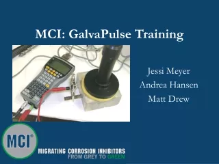
MCI: GalvaPulse Training
350 likes | 388 Vues
Learn how GalvaPulse measures current, resistivity, corrosion rates, and more in concrete structures. Understand the benefits, scope, and steps for GalvaPulse testing.

MCI: GalvaPulse Training
E N D
Presentation Transcript
MCI: GalvaPulse Training Jessi Meyer Andrea Hansen Matt Drew
What is a GalvaPulse? • The GalvaPulse can measure current and resistivity by calculating galvanostatic pulse measurements. • When the galvanostatic pulse measurements are performed the Half-Cell Potential, the Corrosion Rate, and the ohmic Resistance can be determined, all in one operation. • Basically, the GalvaPulse can tell you how much corrosion you have now and the potential for corrosion in the future.
Why Use a GalvaPulse? • Determine Corrosion Rates • Measure Half-Cell Potentials • Predict the lifetime of a structure • Proactively extend your structure’s lifespan • Provide data to show that product is decreasing rate of corrosion compared to control
Corrosion Rate Estimations • Key parameters involved in corrosion rate estimations include the concrete material, rebar conditions, humidity, and temperature. • Using all of this information, lifetime predictions of the concrete can be made.
Scope • Measuring the corrosion rate or half cell potential of reinforcement embedded in concrete. • The galvanostatic pulse measurement technique is a fast polarization technique for determination of the actual corrosion rate at the time of testing.
Preparing for the Test • If rebar is not exposed or visible, it will need to be located using the reinforcement locator. • Hold reinforcement locator away from body in the air (away from concrete and other metals). • Turn on the reinforcement locator until sound is coming up and the red light is turned on. • Turn the knob slightly backwards until the sound disappears. • The locator is now adjusted to its maximum sensitivity. • Locate the centerline of the bars in each direction by means of the sound and the red indicator lamp.
Preparing for the Test • To gain access to rebar after it is located • Drill with the 18mm drill bit to the reinforcement, on the centerline. • Continue drilling with the 12mm drill bit sideward so the drill bit is touching the bar. • Blow the hole free from dust and insert the adapter bolt in the hole with the sloping edge of the bolt resting against the bar. • Turn the bolt firmly with the 10mm Allen key for the threads of the bolt to cut into the bar.
Preparing for the Test • Wetting the Surface Per ASTM C876-91 • It is recommended to wet the surface where testing will take place three times every 15 minutes before testing will begin. • Wetting should be done uniformly at every test point on the grid.
Turning GalvaPulse On • Turn on the GalvaPulse by pressing On/Esc. • The GalvaPulse has an automatic screen shut-off to save battery life. • If Idel is not on top of screen, select FORCE icon and press enter. • If Idel shows on top of screen, press Menu key.
Entering the GalvaPulse Settings • Select SETTINGS • Select TIME • 10 seconds is the default setting for taking GalvaPulse readings and should always be used • Press Enter
Enter Galvanic Pulse Current • Select SETTINGS • Select CURRENT • Range is 5-400 μA. • Default is 25 μA, and is used for passive areas. • For active areas, use 80-100 μA. • For VERY ACTIVE, a current up to 400 μA can be necessary to obtain a reasonable polarization. Always use as low of current as possible to minimize polarization. • Press Enter
Entering Rebar Settings • Select SETTINGS • Select REBAR • Enter DIAMETER in mm and press down • Enter LENGTH in mm and press down • Default is 70 mm, equal to the diameter of electrode (guard ring). • Press down and then Enter • Area will automatically calculate • Press Enter
Entering Guard Settings • Select SETTINGS • Select GUARD • Only turn off if not using guard ring sensor, i.e. rebar is cut at both ends. • If this is the case, you will also need to change the length in rebar settings. • Press Enter
Entering Grid Settings • Select SETTINGS • Select GRID • Default settings will display • If total number of test points is not known, use Default parameters. • Press Enter
Saving Settings • Select SETTINGS • Select SAVE • Press Enter
Creating New Data Files • There are two different data files that can be created: • Half-Cell Potential (HCP) Data Files are used when only the HCP is needed. • GalvaPulse Data Files are used when both HCP and Pulse Readings are wanted.
Creating a New Data File • Select ACTION • Select “New HCP” or “New Pulse” and press Enter. • Select B Drive by using arrows. • B Drive is Cortec’s memory card • Press down arrow and create a file name • Press Enter when finished
Opening Existing Data Files • Select ACTION • Select “Load HCP” or “Load Pulse” and press Enter • Select drive on which file is stored • Find File Name • Press Enter to open file
Taking Measurements • Once surface has been completely prepared and dampened, connect all wires. • Ensure a proper connection of pliers to the exposed rebar. • Pliers may not make a complete connection to the metal surface. • Some sanding may be required if corrosion already exists on the rebar.
Taking Measurements • Wet sponges and insert smaller one into center hole. Attach other sponge to electrode head by mounting the holes in sponge around the three screws. • Place electrode on level concrete surface directly over the same exact rebar to which pliers are connected. • Ensure all three screws are resting against the surface. • Make sure there are no puddles of water.
Taking Measurements • Once the electrode is in place: • Press the arrow keys to change the coordinates of the measuring points (from start point to end point). • Press the M key to start the measurement. • Keep electrode completely steady while count measurement is being made
Taking Measurements • When pulse is finished, a graph will appear in the plot area. • A valid reading shows points increasing over time without a large scatter • A decreasing graph is a sign of a false reading • Repeat measurement, and if graph is still decreasing, adjust settings. • Repeat measurement if large scatter is shown
Trouble with Measurements • If data plot is decreasing, is a scatter, or you receive a pop up screen saying “Please make a new measurement”, repeat measurement in same location. • If several attempts are unsuccessful, testing parameters can be changed in SETTINGS.
Trouble with Measurements • If you are having trouble getting a valid reading, try the following steps, ONE AT A TIME, before retaking a measurement. • Move the electrode to a new spot a few centimeters away and try again • Check connection to rebar and make sure it is clean and tight • Re-wet surface, wait 10 minutes, and try again • Increase the current by a factor of two
A Good Measurement • If a nice, increasing, non-scatter plot is displayed after measurement is made: • Press right arrow to find the next measurement point • Repeat same steps for new point
Interpreting Measurements • The following are characteristics of corroding steel reinforcement: 1) -400 to -500 mV for HCP (Ag/AgCl) 2) 5 to 20 μA/cm2 for Corrosion Current 3) 1-4 KOhm for Electrical Resistance
Interpreting Measurements • The following chart is used to correlate corrosion current, corrosion rate, corrosion level and time to visible deterioration as shown.
Interpreting Measurements • The climate information for the day and weather history should also be included and taken into consideration of interpretation of measurements. One place weather history may be found is www.weatherunderground.com. • Half-Cell Potential (HCP) readings, visual inspections, and comparisons to control areas, etc. are also information that should be taken into consideration of interpretation.
Exiting the Program • Select ACTION • Select EXIT • It is safe to press the OFF button and leave the GalvaPulse in this state. It will start with the same display the next time it is turned on. • Disconnect all wires and place components back into case. • Make sure sponges are removed from electrode to prevent corrosion, but do not seal wet sponges in plastic bag as they will become rotten. • If rings become corroded, they need to be grinded to a smooth finish using emery cloth.
Some FYIs • Changing batteries • GalvaPulse contains two AA batteries and one 3V battery • Do NOT change all three at the same time, for loss of data may occur • Calibration • Instrument should NOT be re-calibrated
Documentation • Documents • Laboratory Reports • Storage • The above referenced quality documents are stored in accordance with the (Document Control SOP) (\\..ReferenceDocuments\ QMS\QualityRecordsMatrix.doc)
References • Manual “GalvaPulse GP-5000 Instruction and Maintenance Manual”, German Instruments, Inc., May, 2005. • Manual “GalvaPulse™ Instruction and Maintenance Manual”, FORCE Technology, 2008 • Binder “GalvaPulse Literature”, German Instruments, Inc., July 2004