Download
1 / 19
190 likes | 212 Vues
This study presents results from edge-TCT and Alibava measurements on microstrip detectors irradiated with pions and neutrons, evaluating charge collection profiles with fluence, annealing, and temperature dependencies. 8 Relevant

E N D
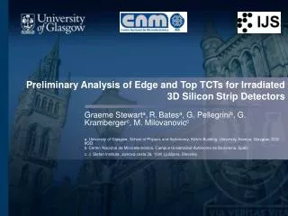
Edge-TCT and Alibava measurements with pion and neutron irradiatedmicro-strip detectors V.Cindro1, G.Kramberger1, I.Mandić1, M. Mikuž1,2, M. Milovanović1, M. Zavrtanik1 1Jožef Stefan Institute, Ljubljana, Slovenia 2Faculty of Mathematics and Physics,University of Ljubljana, Slovenia
Outline • Edge-TCT and Alibava setup, samples • Basics of analysis • Evaluation of charge collection profiles with fluence, annealing and temperature • Conclusions M.Milovanović, 18th RD50 Workshop, Liverpool, UK, 23 – 25May 2011
T=-20°C 1.5 GHz scope • laser • 1060 nm • 100 ps pulse • 200 Hz – 1MHz repetition detectors on a Peltier cooled support in dry air atmosphere (down to -20oC) lens system Edge-TCT setup • Position of e-h generation can be controlled by 3 sub-micron moving tables (x,y,z) • The amount of injected charge can be controlled by tuning the laser power • Not possible to study charge sharing due to illumination of all strips • Absolute charge measurements are very difficult • Annealing done with samples mounted in the setup => the same spot in the detector is illuminated at all times • Measurements performed at different temperatures, from -20 to +10ºC M.Milovanović, 18th RD50 Workshop, Liverpool, UK, 23 – 25May 2011
The Alibava setup • Successful commissioning of the setup utilizing absolute charge measurements using a 90Sr • A Peltier element for cooling and annealing (-40 to 60°C) • Results compared with Edge-TCT and SCT128A and shows very good agreement of all three, which also validates the E-TCT <Q> technique as well. • Problems with Noise M.Milovanović, 18th RD50 Workshop, Liverpool, UK, 23 – 25May 2011
Samples • Measurements of collected charge and leakage current performed at different bias, temperature and annealing steps. M.Milovanović, 18th RD50 Workshop, Liverpool, UK, 23 – 25May 2011
Charge collection and velocity profiles CHARGE COLLECTION PROFILE RD50 Micron p-type sensor Vfd~16 V VELOCITY PROFILE charge collection for mip M.Milovanović, 18th RD50 Workshop, Liverpool, UK, 23 – 25May 2011
HPK – non-irradiated • At 200V, detector is fully efficient • Double junction visible for V<Vfd • Growth of “active region” with bias can be observed (agrees with homogenous Neff) • The current pulses show expected behaviour • The <Q> plot validates the method M.Milovanović, 18th RD50 Workshop, Liverpool, UK, 23 – 25May 2011
HPK – Φeq=1∙1015 n/cm2 • Charge collection profiles show increase of both active and “un-active” region of the detector with higher bias. • Electric field at the back is much smaller than at front; “double junction effect” is smalldue to oxygen lean detectors and neutron irradiations • No evidence of charge multiplication • CC for forward bias is very high, even at low voltages, mostly due to long drifts of charge carriers • The detector is active throughout the whole detector depth - efficiency is best at it’s centre M.Milovanović, 18th RD50 Workshop, Liverpool, UK, 23 – 25May 2011
HPK – Φeq=1∙1015 n/cm2 • The border of the “depleted-active region” and “active bulk” determined from intersection of the two lines • Charge collection Q(y) and the active show expected increase with annealing up to 80min at 60°C;the active region increase: ≈35μm at 500V, as predicted • <Q> profile shows ~30% of CC increase at 800V • High charge collection in forward bias even at very low voltages; at 50V CC more than 50% of CC at 800V reverse bias. M.Milovanović, 18th RD50 Workshop, Liverpool, UK, 23 – 25May 2011
HPK – Φeq=1∙1015 n/cm2 • <Q> profile vs. temperature shows almost no change • However, charge collection profiles at different temperatures show: • Increase of “non-active” region with temperature (due to better detrapping?) • Decrease of CC in the active region (higher Vfd due to change of Neff, higher generation current?..) • These two effects obviously even out, causing no significant change in <Q> M.Milovanović, 18th RD50 Workshop, Liverpool, UK, 23 – 25May 2011
HPK – Φeq=2∙1015 n/cm2 • The “active region” is reduced with respect to higher fluence, as expected • Charge collection in the “non-active” region becomes significant • Forward bias shows better CC and stable profile. M.Milovanović, 18th RD50 Workshop, Liverpool, UK, 23 – 25May 2011
HPK – Φeq=2∙1015 n/cm2 • The active region decreases with fluence, as predicted • <Q> profile shows virtually no increase after annealing in reverse bias • Forward bias positively influenced by the annealing M.Milovanović, 18th RD50 Workshop, Liverpool, UK, 23 – 25May 2011
HPK – Φeq=2∙1015 n/cm2 Estimated Vfd (denoted by line) 2270 V 3650 V • <Q> profile vs. temperature shows almost no change for reverse bias – the same mechanism as with previous irradiation step • Estimations of the active regions show pretty good correspondence with the estimated values (≈10%) • The difference due to the “non-active” region M.Milovanović, 18th RD50 Workshop, Liverpool, UK, 23 – 25May 2011
HPK – Φπ=4.14·1014cm-2(Alibava) • Low depletion voltage (Vfd≈300V instead of expected ~940V ) • The detectors were already annealed during the irradiations @PSI, at T=26°C (108h for this detector) • Low and stable current in agreeement with expectations M.Milovanović, 18th RD50 Workshop, Liverpool, UK, 23 – 25May 2011
HPK – Φπ=4.14·1014cm-2(Edge-TCT) M.Milovanović, 18th RD50 Workshop, Liverpool, UK, 23 – 25May 2011
HPK – Φπ=1.42·1015cm-2(Edge-TCT) • A non-square charge collection profile most likely shows different trapping effects for electrons and holes • Again, we see a large CC for forward bias due to long drift of charge carriers. M.Milovanović, 18th RD50 Workshop, Liverpool, UK, 23 – 25May 2011
HPK – Φπ=1.42·1015cm-2(Edge-TCT) • Virtually no influence of short-term annealing for reverse, and forward bias. • Velocity profiles confirms that only trapping difference between e and h can be the cause for such a charge collection profile M.Milovanović, 18th RD50 Workshop, Liverpool, UK, 23 – 25May 2011
HPK – Φπ=1.42·1015cm-2(Edge-TCT) • The leakage current remains stable. • Temperature scan shows difference only in forward bias, however, the underlying change of Vfd is vissible in charge collection profiles • Change in Vfd≈100V! M.Milovanović, 18th RD50 Workshop, Liverpool, UK, 23 – 25May 2011
Conclusions • Vfd retains the validity as the parameter determining active region (high CCE region) up to 1-2∙1015 cm-2 for neutron irradiated HPK sensors • Substantial electric field is present in whole detector at high fluences already for moderate voltages • The difference between efficiency of different regions in the detector is reduced with fluence • Short-term annealing affects the detector performance in positive way • before significant contribution from amplification the beneficial annealing is similar to the predicted from low fluence data • Pion irradiated samples show: • Very small Vfd • Trapping effects for electrons and holes seem to be different for higher fluence, resulting in distorted charge collection profile • Full depletion voltage significantly changes with temperature (~100V) • Future plans • More measurements with HPK sensors and Micron RD50 run (p-on-n, n-on-p and n-on-n) • Studies on mixed irradiated sensors (pion+neutron) • Edge-TCT parallel with strips (charge sharing, weighting field impact) M.Milovanović, 18th RD50 Workshop, Liverpool, UK, 23 – 25May 2011