Download
1 / 61
620 likes | 643 Vues
Learn about proper dimensioning techniques and the importance of signs and symbols in conveying information clearly and universally. Understand how to create dimensioned drawings to British Standards and recognize common signage symbols. Dive into the world of signs, including warning signs, prohibition signs, mandatory signs, safety signs, and more! Master the use of symbols in flow charts and diagrams for effective communication. Enhance your knowledge to create accurate and informative visual representations.

E N D
National 4/5Graphic Communication Signs & Symbols Dimensioning Scale Drawings
Dimensioning • We dimension objects to show what size they are. • This is vital when we pass our drawings onto a craftsperson to make the object.
Dimensioning • Dimensions are drawn to British Standards. • This means that all dimensions are always drawn the same way. • Dimensions you show will always be measured in millimetres so you do not have to show units.
Dimensioning Horizontal dimensions are read from the bottom of the page. 50
Dimensioning Vertical dimensions are read from the right-hand side of the page. 40
Dimensioning 40 Vertical dimensions are read from the right-hand side of the page.dimension figures should never touch the outline of the object. 40
Dimensioning Leader lines are used to bring the dimension away from the drawing. There should always be a gap left between the object and the leader line. 40
Dimensioning The arrowheads used on the dimension line should be kept small and slim and the point of the arrowheads should touch the leader lines. 50
Dimensioning Larger dimensions should be drawn further away from the object. 100 25 25 25 25 Smaller dimensions like these should be placed in line.
Dimensioning When dimensions are taken from one leader line then this would be called a datum line 30 10
Dimensioning The symbol Ø stands for diameter. Ø45 Circles should always be dimensioned to show their diameter.
Dimensioning The symbol r stands for radius. r20 Curves should always be dimensioned to show their radius.
Dimensioning - Rules • Show a dimension only once. • Dimensions should only ever be read from bottom or the right-hand side of the page. • All sizes are shown in millimetres. • Your dimensioning figures should never touch or interfere with any part of the drawing. • Ø is the symbol used to show a diameter, while r is used to show a radius. • Show the diameter of circles. • Show the radius of curves.
Signs • Signs are used to convey information in pictorial form. • This has many advantages over written instructions. • People who talk different languages can understand the same common signs. • Instructions for some tasks can be clearer when given as drawings.
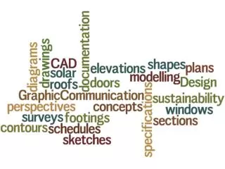
Signs & Symbols • Signs & symbols are commonly used in everyday situations. • Roadsigns, information, engineering symbols, flow charts and circuit diagrams are types of drawings that are used to communicate graphically everyday.
Warning signs • Warning signs are triangular in shape. They have a black border, a yellow background and a black symbol. • They warn people of hazards that could cause personal injury or pose a threat to peoples’ health. General warning sign
Prohibition • Signs & symbols are commonly used in everyday situations. • Roadsigns, information, engineering symbols, flow charts and circuit diagrams are types of drawings that are used to communicate graphically everyday.
Mandatory • Signs & symbols are commonly used in everyday situations. • Roadsigns, information, engineering symbols, flow charts and circuit diagrams are types of drawings that are used to communicate graphically everyday.
Safe condition • Signs & symbols are commonly used in everyday situations. • Roadsigns, information, engineering symbols, flow charts and circuit diagrams are types of drawings that are used to communicate graphically everyday.
Fire safety • Signs & symbols are commonly used in everyday situations. • Roadsigns, information, engineering symbols, flow charts and circuit diagrams are types of drawings that are used to communicate graphically everyday.
Signs - Kitemark • The Kitemark is used to tell consumers that the products they buy are safety tested to BSI standards. • All products sold must carry this Kitemark to be legally sold. The British Standards Kitemark.
Signs - Fragile • This mark is placed on breakable objects’ packaging to tell people handling the box to treat it with care. The Fragile symbol.
Signs - Recycled • This mark is placed on recycled objects to tell the consumer that they are buying a recycled product. • This is a big advertising point as companies like their products to be seen as being environmentally friendly.
Signs - Disabled • This is used to show disabled access.
Signs - male & female • These signs are used commonly to distinguish the male and female toilets.
Flow Charts • A Flow Chart is a method of showing the correct steps to follow in order to complete some type of problem. • There are some symbols used in flow charts to show certain processes that have to be done when completing the problem.
Process Input/Output Decision Flow Charts • These symbols are shown below. Start/Stop
Has button been pushed? No Yes Wait 2 Start Amber light flash Wait 5 Amber light on Red light off Red light on Green light on Wait 10 Flow Charts • An example of a flow chart for a pelican crossing is shown:
Drawing Symbols • Drawings use many different line types to show different parts of an object. • These are standardised so that anyone can understand what is meant by a particular line type regardless of where they come from.
Drawing Symbols • Orthographic drawings are drawn in Third Angle Projection. • This is a standard drawing layout covered in the tutorial on orthographic projection where the 3 views are drawn in the direction you are looking at them.
Drawing Symbols • The 3rd Angle Projection symbol is shown below. • This is normally included on a drawing to tell people the standard it is drawn in.
Drawing Symbols • Different line types used include: • outlines • projection lines • hidden detail • centre lines • cutting planes • fold lines
Drawing Symbols - Outlines • Outlines are used to show the outline of an object. • They are thicker than projection lines. • Drawn at 0.7mm thick.
Drawing Symbols - Projection Lines • Projection lines are used to help construct a drawing. • They are not part of the outline of the drawing and are drawn lightly and thin.
Drawing Symbols - Hidden Detail • Hidden detail lines are used to show any part of an object that cannot be seen but does exist. • They are dashed lines.
Drawing Symbols - Centre Lines • Centre lines are used to show the centre of circles or lines of symmetry. • They are drawn as a series of long and short dashes.
Drawing Symbols - Cutting Planes • Cutting planes are used to show where an object is cut in a sectional drawing. • The arrows tell us what direction the cut is to be viewed. • The letters are the label of the section. • The ends of the cutting plane are drawn slightly thicker than the rest of it. X X
Drawing Symbols - Fold Lines • Fold lines are used to show where surface developments should be folded.
Building Symbols • Engineers need to use symbols to show the different materials used in building a house. • This is law as when submitting planning permission a company must be able to prove the quality of the houses or buildings they want to build.
You need to know each of these symbols shown. • When asked a question in your exam you will have to name each symbol with the exact name shown below. Building Symbols
Storyboards • Storyboards give step by step instructions on how to operate something using pictures to illustrate what is to be done at each stage. • Short statements further help the user understand what to do. • They are often found on change machines and in electrical appliance instructions.
Storyboards • These are advantageous as a person does not have to speak any specific language to understand what to do. • The written instructions are kept very short which helps people who, for any reason, cannot read things properly. • Often the statements are also given in many different languages to help foreigners.
Building drawings • A number of different drawings are required to be completed and submitted to the local authorities when developers want to build new buildings. • This group of drawings is called a Project Set.
Project Set • A project set consists of a number of different drawings including • elevations • sketches • sectional drawings • schematic diagrams • location plans • site plans • floor plans
Project Set • Elevations, sketches and sectional drawings are required to view the actual building. • Schematic diagrams are used by tradesmen to install any electrical circuit work or plumbing and heating. • Schematic diagrams use British Standards symbols covered in these slides.
Location Plans • This type of drawing shows the position of the new building in its surrounding area. • It is as if you are looking at the building from an aeroplane above. • It is normally drawn to a scale of 1:1250.
Location Plans • This is an example of a location plan. Albany Terrace Albany Drive Albany Road
Site Plans • This type of drawing shows the building from closer in than a Location Plan. • It is like a bird is looking down at it. • It shows the building in its immediate surrounding area. • It is normally drawn at a scale of 1:200.
8.5 5 12.5 7 2 Glenisla Drive Site Plans • This is an example of a site plan.
Floor Plans • This type of drawing shows the internal layout of a building including the materials used in the walls. • Any electrical appliances fitted will also be drawn like, radiators, electrical sockets and switches. • This type of drawing is normally drawn at a scale of 1:50.