Download
1 / 24
240 likes | 372 Vues
This report presents the efforts of the CERSER Grounding Line Validation Team in accurately determining the grounding line of the Antarctic ice sheet, crucial for understanding its dynamics and mass balance. Led by Dr. Malcolm LeCompte, the team utilized LANDSAT 7 data from 2003 and older LANDSAT imagery to analyze changes in coastal regions, particularly at Pine Island Glacier and the Larsen Ice Shelf. The study assesses the accuracy of the grounding line established during the ASAID project and investigates potential changes over time, contributing to climate-related ice sheet research.

E N D
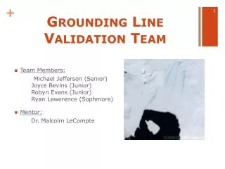
Grounding Line Validation Team • Team Members: Michael Jefferson (Senior) Joyce Bevins (Junior)Robyn Evans (Junior)Ryan Lawerence (Sophmore) • Mentor: Dr. Malcolm LeCompte
Overview • Abstract • Introduction • Determining the Grounding Line • Results • Future Works • Conclusion
Abstract Dynamics and mass balance of an ice sheet can be derived from an accurate measurement of its area. To measure the area of a continental ice sheet, the grounding line must first be accurately determined. The grounding line is the boundary between the ‘grounded’ ice resting on land and any associated floating ice comprising a retaining ice shelf. During a project entitled Antarctic Surface Accumulation and Ice Discharge or ASAID, Dr. Robert Bindschadler, lead an international team of glaciologists and computer scientists, including ECSU students, in an effort to obtain a more accurate measure of the area of the Antarctic ice sheet and determine its mass balance. That is, whether the amount of ice is growing or diminishing over long time intervals. Bindschadler’s team determined the grounding line using methods of photoclinometry with LANDSAT Enhanced Thematic Mapper (ETM) image brightness and surface elevation data from the Geoscience Laser Altimeter System (GLAS) aboard NASA’s Ice, Land and Cloud Elevation Satellite (ICESat). The ASAID grounding line (GL) was established using LANDSAT 7 and GLAS data obtained in 2003. However its accuracy and utility had not been tested. With the current ASAID 2003 Grounding Line (GL), the CERSER GL Validation Team was tasked by Dr. Bindschadler with determining its accuracy in two coastal regions and whether changes have occurred over long time intervals. The team over-laid the 2003 GL on LANDSAT Seven ETM imagery temporally proximate to 2003. This modified image was then compared to decades older LANDSAT 4 & 5 Thematic
Abstract Cont’d Mapper (TM) imagery. GL validation and change determination were planned for two geographic areas known to exhibit rapid changes potentially due to climate warming: Pine Island Glacier (PIG) and Larsen Ice Shelf. However, due to time constraints, the team only examined a limited portion of the PIG. The GL was tested along a portion of the Antarctic coast near the PIG. To accomplish the validation, LANDSAT 7 images from 2003 used in creating the GL, were obtained from the USGS archive (lima.usgs.gov). Other LANDSAT images were obtained from the USGS GLOVIS on-line archive (glovis.usgs.gov). The oldest possible, cloud-free LANDSAT 4 and 5 TM images were obtained for the regions of interest. To facilitate data manipulation and image comparisons, the extremely large GL vector file, obtained from Dr. Bindschadler. was truncated to include only the geographic regions of interest. Truncation and image comparisons were accomplished using ITT Visualization System’s ENVI image processing software. Any departure from perfect geographic pixel registration was corrected by using the 2003 image as a reference and then warping the older image to conform to the common fixed control points visible on both images. The grounding line overlying the 2003 image was then examined and compared to the older image. The geographic coordinates and extent of any departures from coincidence were recorded and reported. A possible deviation in the GL was found while comparing a 2001 LANDSAT 7 image to a 1986 LANDSAT 5 image, near a small glacier feeding into Pine Island Bay. Comparison with a 2003 image of the same area revealed no GL inaccuracy; however a small ice shelf appeared to have progressively diminished over time until it disappeared in 2003.
Key Terms • Landsat 7 ETM+ (Enhanced Thematic Mapper Plus) – multispectral scanner instrument on the Landsat 7 satellite used to collect the image data used in GL validation research • GloVis (Global Visualization Viewer)- USGS online archive used to store Landsat imagery • LIMA (Landsat Image Mosaic of the Antarctic) - provided 2003 images used to define the GL • PIG (Pine Island Glacier) the area of interest for the grounding line investigation • Grounding Line - the last portion of an ice sheet that is supported by land before it becomes a floating ice shelf • Hinge Point - the inflection point between ice shelf and ice sheet • Ground Control Points - a system of distinct geographic features that is recognizable on images and used to facilitate image to image pixel registration
Objectives • Overlay the GL vector file on the 2003 Landsat image used to create it and check for topographic consistency • Is it landward or seaward of an apparent coastline? • Investigate whether the GL can be used as a tool to investigate long term changes in coastal topography. • Compare 2003 GL and Imagery with older Landsat images
Diagram of the GL • Illustration shows grounding line, ice shelf • In the teams research, the inflection point would be between the glacier and the ice shelf • The ice shelf is subject to tides and waves Image from: www.google.com
Envi • The ENVI product family provides a variety of software solution for processing and analyzing geospatial imagery used by scientists, researchers, image analysts, and GIS professionals around the world. • Envi was used to display, georectify, and compare images in order to determine if there were variations in the grounding line
Overlaying Grounding line on Landsat image • Obtained grounding line vector file from Dr. Robert Bindshadler working at NASA Goddard in Greenbelt, Maryland • The grounding line was created using LIMA images from 2003 • The specific image for PIG was obtained from the LIMA dataset
Pine Island Glacier Lat:-74, Long: -101 Path: 001 Row: 113 ASAID grounding line
Does the Grounding Line Fit? • Before continuing the research, validation of the grounding line was needed to see if it was a correct match • After the comparison, the grounding line fit the image perfectly
Objective Two: Can the GL be used as a tool to determine temporal changes to coastline?
Investigation of the Grounding Line • LIMA website had no single image that covered the entire area of interest • PIG a mosaic of path/row (Latitude delimiter/ Longitude delimiter) : 233/113 and 233/114 • Those LIMA images did not have early Landsat counterparts • GloVis was used to obtain Landsat images (001/113)from 2001 possessing older counterparts • Since grounding line was georeferenced with its LIMA imagery, image to image registration was required
Image to Image Registration • 2001 image was chosen as the geographic reference for registration • Common geographic points (five) were selected in both the reference image and the one to be registered • ENVI provides the image to image registration process that co-registers image pixels at common geographic points in each image
Truncation of the Grounding Line • After completing the validation of the grounding line and warping the 1986 image, problems started occurring • The grounding line was a very large file • Took a while to load • Frequently caused freezes and crashes • Slowed image to image comparisons • The solution to this problem was to truncate the GL to the area containing Pine Island Glacier
Truncating the Grounding Line • Used an ENVI tutorial detailing creating a new polygon file • Wanted to get as accurate as possible to the grounding line • Opened the original grounding line and and overlayed it on the area of interest • Tediously picked points on the line and created a new file that was smaller and could be opened in a timely manner
Making the Comparison • ENVI was used to display the GL as a vector overlay on the 2003 and 1986 satellite images • The images were linked allowing an overlapped display of one co-registered image upon another • With this utility changes over time could be readily viewed
2001 vs. 1986 This shows a comparison between the 2001 vs. the 1986 warped image These are the ground control points that allow the image to be georeferenced
2003 vs. 2001 This shows a comparison between the 2003 vs. the 2001 image
Results • GL was an accurate depiction of the 2003 coastline • From 1986 -1989 - 2001 there was an ice shelf retreat until its dissipation in 2003 • Confirmation from Dr. Robert Bindshadler shows that our research uncovered a retreating ice shelf
Future Works/Conclusions • Due to time constraints we only investigate a small section of Pine Island Glacier • Further investigation of unexamined portion of the Pine Island Glacier coastline might show variations in the retaining ice shelf or changes in the grounding line itself • Larson Ice Shelf remains to be investigated • Implement new software beta test • New NASA Goddard software to investigate GL
References/Acknowledgements • GloVis: Glovis.usgs.gov • LIMA: lima.usgs.gov • ENVI: http://www.ittvis.com/language/en-us/productsservices/envi.aspx • Dr. Robert Bindshadler, Glaciologist at NASA Goddard