Download
1 / 17
170 likes | 320 Vues
Pinning Mode Resonances of 2D Electron Stripe Phases in High Landau Levels. Han Zhu ( 朱涵 ) Physics Department, Princeton University National High Magnetic Field Laboratory, Florida State University G. Sambandamurthy, NHMFL/FSU&Princeton EE, now SUNY buffalo

E N D
Pinning Mode Resonances of 2D Electron Stripe Phases in High Landau Levels Han Zhu (朱涵) Physics Department, Princeton University National High Magnetic Field Laboratory, Florida State University G. Sambandamurthy, NHMFL/FSU&Princeton EE, now SUNY buffalo Pei-Hsun Jiang, NHMFL/FSU&Princeton EE R. M. Lewis, NHMFL/FSU, now U Maryland Yong Chen Princeton EE&NHMFL/FSU, now Purdue L. EngelNHMFL/FSU D. C. Tsui, Princeton EE L. N. Pfeiffer and K. W. WestBell Labs, Alcatel-Lucent
AlxGa1-xAs 2D electron systems GaAs 10~50 nm AlxGa1-xAs Electron mobility (cm2/Vs) -2007 45 m -2005 30 m -Late 90’s, 10 m -80’-90’, 1 m -1980, 100 k • Fractional Quantum • Hall Effect of Composite Fermions • Stripes, Bubbles, etc. • Non-Abelian states • Fractional Quantum • Hall Effect • Integer Quantum • Hall Effect
CDW in Quantum Hall systems Landau Level filling ν> 4 easy IQHE-Wigner Crsytal hard R_yy 4 9/2 R_xx Fogler et al. ’96, R. Moessner, and J. T. Chalker, 96’ Lilly et al, ’99 ...
Different viewpoints on the stripe phase nematic Stripe crystal smectic Also, elliptical Fermi surface... Oganesyan, Kivelson, Fradkin’01 A review available by Fogler in cond-mat . . .
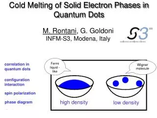
Wigner crystal: Pinning modes B In high B, at low filling factors, electrons form a Wigner crystal fpk is a measure of average pinning energy per electron; pinning energy lowers overall energy
Outline • Microwave/rf measuring technique • Stripephase: anisotropic pinning mode • Stripephase in In-plane field: Turns resonances on and off Interpretation: pinning energy measured by resonance frequency
Microwave/Rf spectroscopy W=78 mm • Metal-film coplanar waveguide Erf Re(xx) = (1/NZ0)ln(P/P0)
n = 2.61011 cm-2 μ= 2.9107 cm2/Vs T ~ 35 mK [110],“x”, “hard” [110], “y”, “easy” bubble Spectra 4<ν<5 stripe bubble Predicted ν range: Shibata& Yoshioka, PRL ’01
Spectra 4<ν<5 : overview [110], “y”, “easy” [110], “x”, “hard” bubble stripe bubble
ν =9/2 in BipDC transport: y, [110] Lilly et al., PRL, 1999 x, [110] R_yy DC experiments: Pan et al., PRL, ‘99 & PRL, ‘00; Lilly et al., PRL, ’99; Zhu et al., PRL, ‘02; Cooper et al., PRL, ‘04 etc. and more... Bip R_xx • (Finite thickness) Bip - induced anisotropy energy • CDW picture • Finite layer thickness • Favors stripe Bip • Jungwirth et al. PRB 99’; Stanescu et al. PRL 00’. Bip
Sample Flexible transmission line Coax cable Rotator Probe for Microwave/Rf spectroscopy Bip=0 stripes Four cases: y, [110] _xxor _yy Bip || x or y x, [110]
Bip=0 stripes y, [110] x, [11̅0] Bip along y Bip Resonance switches from xx to yy around Bip=1 T Bip brings up fpk of resonance in xx
Bip=0 stripes y, [110] x, [11̅0] Bip alongx Bip
Peak Conductivity y, [110] x, [110] Bip Bip
Peak Frequency Bip Bip
What can be determining the stripe orientation • Native Anisotropy • not understood, weak, sample dependent • Finite thickness Bip - induced anisotropy energy • Calculated from CDW, finite layer thickness, • Favors stripe Bip Jungwirth et al. PRB 99’; Stanescu et al. PRL 00’ • Measured by us: Pinning energy anisotropy • Disorder-carrier interaction, • Bip dependent: increases with Bip • Favors stripe | | Bip K B Cooper et al.. Solid State Comm 119 89 (2001) 30 nm QW, 2.7 1011/cm2 Pinning energy is relevant to determining stripe orientation!
Bip along x Summary yy • Stripe phase resonance • Hard direction 100 MHz, pinning mode interpretation • Apply Bip: • switches resonance direction • fpk increase with Bip • measure of pinning energy xx