NETWORK DESIGN
NETWORK DESIGN. Customer requirements Network topologies Cable choice Hardware TSB 75 TSB72. Customer Requirements. Nature of traffic Email Video Security Of data Of closets EMI Fluorescent lighting Motors. Site Campus Occupied Listed Run lenghts Future proofing Bit rates

NETWORK DESIGN
E N D
Presentation Transcript
Customer requirements • Network topologies • Cable choice • Hardware • TSB 75 • TSB72
Customer Requirements • Nature of traffic • Email • Video • Security • Of data • Of closets • EMI • Fluorescent lighting • Motors • Site • Campus • Occupied • Listed • Run lenghts • Future proofing • Bit rates • EMI • Security
Customer Requirements • Cost • Installation • Maintenance • Long V's Short term • Environment • Open plan • Office • Rearrangement frequency
Network Topologies • CHOICE OF TOPOLOGY DEPENDS ON • LAYOUT OF BUILDING • AMOUNT OF EQUIPMENT TO BE CONNECTED • TYPE OF EQUIPMENT TO BE CONNECTED • PERFORMANCE REQUIREMENTS • COST
Network Topologies • POINT TO POINT TOPOLOGY • DIRECT CONNECTION BETWEEN TWO PIECES OF EQUIPMENT
Network Topologies • BUS TOPOLOGY • NODES CONNECTED TO A SINGLE WIRE • PROBLEMS DIFFICULT TO ISOLATE • MAIN CABLE FAILS ENTIRE NETWORK FAILS • EASY TO MODIFY
Network Topologies • STAR TOPOLOGY • SEVERAL DEVICES OR NODES CONNECTED TO A CENTRAL HUB • RELIABLE • ONE MALFUNCTIONING NODE DOES NOT UPSET THE REST OF THE NETWORK • FLEXIBILITY • NODES CAN BE ADDED OR REMOVED WITHOUT DISRUPTING SYSTEM • MORE CABLE REQUIRED THAN A RING OR BUS TOPOLOGY
Network Topologies • RING TOPOLOGY • NODES CONNECTED IN CLOSED LOOP • DATA PASSED FROM NODE TO NODE TO TARGET DESTINATION • NODE FAILS - NETWORK MAY FAIL • ADDITION OF NODE ONLY WHEN NETWORK INOPERATIVE
Network Topologies • PHYSICAL STAR • RING CONFIGURATION • STAR TOPOLOGY
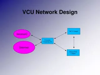
Network Topologies • COLLAPSED BACKBONE • SIMILAR TO STAR
Network Topologies • SHARED NETWORK
Network Topologies • SWITCHED NETWORK
Cable Choice • UTP • FTP, STP, ScTP • Wireless • Fibre
UTP • Horizontal • EMC (Electromagnetic Compatibility) • Not resistant to EMI • Crosstalk • Not secure • Cheap • Carries up to Gigabit speeds • Distances
Screened • FTP, STP, ScTP as with UTP but • Better resistance to EMI • Better resistance to Crosstalk • Needs grounding • More expensive (labour)
Wireless • Shared 54Mbps channel • Ease of installation • No cable • Susceptible to EMI
Fibre • Multimode • Singlemode • Secure • Cost • Distances • Bandwidth
Hybrids • Copper • Fiber • Multimode / Singlemode • Future proofing • Cost
Switch • Central component of star topology • Regenerates and repeats data • Extended distances • Dedicated bandwidth • Switching • Same media (e.g.. Ethernet)
Router • Connects two LANs together • Routes data from source to destination • Reduces network traffic • Improves performance • Relatively high cost • Extended distances • Mixed media (e.g. Ethernet & token ring) • Mixed protocols (.eg. TCP/IP & Novell IPX)
Consolidation point • Zone distribution • Open office cabling • Consolidation point • Must be at least 15m from telecomms closet • Should be limited to serving a maximum of 12 work areas. • Located is fully accessible, permanent locations • Was known as TSB72 in EIA standards
TIA/EIA-568-B.1 6.4.2Consolidation point (TSB 75) • Advantages • Transition point allowed along 90m • Office divided into zones • Only short run at transition point moved when office moves • Less disruption • Less lost productivity • Work area leads can be lengthened if run is less than 90m • Is not meter for meter (see table) • Leads have higher attenuation
Patch leads • The connection from the CP to the TO uses solid core copper. • The option is available to use a stranded cable but the total maximum length of your link is reduced • Stranded cable has 20% higher attenuation so the total length of your link must be reduced • Option to use a 26AWG cable • 50% higher attenuation • must adjust figure in table accordingly
11801 and TIA/EIA-568-B.1 • Centralised Optical Architecture • Previously called TSB 72 • Usually for fibre systems • Can use copper • 300 meter length limit (including patch cord in TIA/EIA version only) • ISO have 3 link lengths of 300, 500 & 2000 m • Also a number of application link lengths • Electronics on one floor • Higher densities on hubs • Less space used