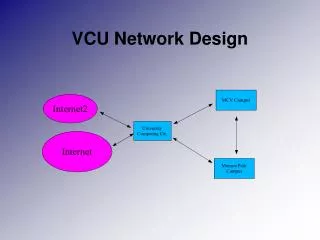
NETWORK DESIGN
OSSD/PSS JANUARY 2006. Confidential, Internal Use Only. NETWORK DESIGN. Network Design Key rule. Computer network and video surveillance network should be separated network. 2. Build video surveillance network should be faster networks.


NETWORK DESIGN
E N D
Presentation Transcript
OSSD/PSS JANUARY 2006 Confidential, Internal Use Only NETWORK DESIGN
Network Design Key rule • Computer network and video surveillance network • should be separated network. 2. Build video surveillance network should be faster networks. 3. Consider network stability and expandability
Network Design Step Figure out maximum bandwidth for each camera (Based on Resolution, Compression and Frame rate) Figure out maximum bandwidth for each client (PC) Planning Network topology Study bandwidth allocation Evaluate network device performance (Capability of transmission packet, function)
Figure out maximum bandwidth for each camera 1.Resolution PAL (WV-NP472, NS320, NW470S) 752x568 NTSC (WV-NP472,NS324,NW474S) 640x480 752x280 640x240 368x280 320x240 176x136 160x120 WV-NP244 640x480 320x240
Figure out maximum bandwidth for each camera 1.Resolution WV-NP1000/1004 1280x960 960x720 1290x960, 960x720 JPEG Only 640x480 320x240
Figure out maximum bandwidth for each camera 2.Compression JPEG MPEG4 Compress Compress 1/15 | 1/120 1/6 | 1/15 1/10 | 1/50 1/6 1/8 1/10 1/12 MPEG4 data-stream widely changes according to the movement of the actual surveillance object. (whether the objects are moving more or less)
Figure out maximum bandwidth for each camera 3.Frame Rate 30 image / second (30 ips) 15 image / second (15 ips) 1 image / second(1ips) Camera has maximum frame rate at expected resolution and compression.
Figure out maximum bandwidth for each camera 1. Calculate Bandwidth for each camera Bit 8 Resolution Frame Rate Compression Color signal 1.5 Bandwidth (Mbps) × × × × = Example Bit 8 Resolution 704x480 Frame Rate5 Compression 1/6 Color signal 1.5 Bandwidth (Mbps) 3.4 × × × × = *A bandwidth calculator helps to determine the bandwidth a network video product will use, based on the image size and frame rate. 2. List All Planning camera Bandwidth
Figure out maximum bandwidth for each camera Maximum frame rate With resolution and Compression NTSC (WV-NP472,NS324,NW474S) **values will change based on condition. PAL (WV-NP472, NS320, NW470S)
Figure out maximum bandwidth for each client The value will be changed by condition. Example Frame rate 12 Resolution 640x240 Quad 4 Compression 1/8 Bandwidth (Mbps) 10.8 × × × = Client PC WJ-ND300 Camera(JPEG) 10.8Mbps
Planning network topology 1.Make network connection diagram. Ex. Camera 16pcs PC clients 4 Hub 12
Planning network topology 2.Make Bandwidth allocation map, Check highest bandwidth point. Evaluate the load to the network device. Balloons show segment bandwidth.
Evaluate network device Requirement of network device for video surveillance network. 1, Managed Switching HUB. (Layer 2 SW). 2, Support wire speed. 3, Port-Mirroring for network performance investigation. 4, Furnish SNMP for easy maintenance.
Evaluate network device About wire speed A switch is said to work at "wire speed" if it has enough processing power to handle full ethernet speed at minimum packet sizes (64byte). Most switches on the market are well ahead of network traffic capabilities supporting full "wire speed" of ethernet, 148,810 pps (packets per second) at 100Mbps, and 1,488,100 pps at 1Gbps. Minimum packet 64byte + 20 byte =84 byte = 672 bit 100Mbps = 100,000,000bps / 672 bit = 148,810 pps 1Gbps = 1,000,000,000bps / 672 bit = 1,488,100 pps Cisco 2960 specification sheet 1Gbps 24ports 100Mbps 1,488,100pps 148,810pps 148,810pps(100Mbps) x Number of port (24) = 3,571,440pps 1,488,100pps (100Mbps) x Number of port (2) = 2,976,200pps Total = 6,547,640 (6.5Mpps)
Evaluate network device About Port Mirroring "port mirroring", which is a feature that enables switches to forward any packet to one PC and allows the network manager to determine the location of a problem on his network simply and efficiently. Port Mirroring is configured by assigning a port (called "management port") from which to copy all frames, and a port to which to send those frames. Finally, when the feature is activated, all frames bound for or sourced from the selected source port will be copied and sent (in addition to their regular destinations) to the selected destination port. Simply by placing a sniffer or ethereal on this destination port, each segment can be separately monitored without moving the equipment. By using this feature, you will able to monitor the entire LAN segment. Same packet monitor the packet
Evaluate network device About SNMP The Simple Network Management Protocol (SNMP) is an application layer protocol that facilitates the exchange of management information between network devices. It is part of the Transmission Control Protocol/Internet Protocol (TCP/IP) protocol suite. SNMP enables network administrators to manage network performance, find and solve network problems, and plan for network growth. monitor the traffic load on network
Evaluate network device Typical L2 switch products.
HUB HUB Network design Tips #1 Flooding When Decoder leave the network all Video stream distribute on all ports. Mac address should be registered in L2 SW Filter table
Network design Tips #2 Gateway Broadcast domain ND300 support only one GW at first release Broadcast domain Broadcast domain
Design Example Scenario Facility Office Building Camera 31pcs PC4 clients
Design Example 1.Calculate all camera bandwidth
Design Example 2.Making Network topology
Design Example 3.Check Bandwidth allocation map,
OSSD/PSS JANUARY 2006 Confidential, Internal Use Only NETWORK FUNCTIONWJ-ND300
WJ-ND300 Network Function Camera server Web server FTP server DNS Client WJ-ND300 Network Function DDNS Client SNMP Agent FTP Client DHCP Client SMTP Client NTP Client
WJ-ND300 Network Function Collect video data from camera on network for live viewing distribution and recording. Camera server
WJ-ND300 Network Function Web server Web browser • URL(Http://192.168.0.250) • WEBPage Various Function
WJ-ND300 Network Function FTP server FTP Client • Archive option • - ND300 FTP server function • Manual request JPEG • Image Data • Alarm log Data AS65 & FTP Client Viewer software Image data • Schedule request *Disk#, Time & Date, camera#, • Archive option • - ND300 FTP server function JPEG • Image data WV-AS65 Image data • - ND300 FTP client function • Archive option * Alarm JPEG • Alarm associated image data AS65 & FTP Server Image data
WJ-ND300 Network Function SMTP Client • - ND300 E-mail Client * Alarm • Alarm associated image data Client E-mail Server Client Simple Mail Transfer Protocol E-mail notification : Send E-mail (Notification + Still image data, Error status)
WJ-ND300 Network Function SNMP Agent A protocol that enables a Network Manager to configure, monitor,and receive trap (alarm) messages from ND300. • - Network Manager • - HD300 SNMP Agent Management Information ◆Equipments and Version ◆Vender ◆Up time ◆Contact person Information ◆Device name on Network ◆Location ◆Service ◆MAC address ◆IP address ◆System Log ◆Error log ◆HDD Hour Meter
WJ-ND300 Network Function Dynamic Host Configuration Protocol DHCP Client • - ND300 DNS Client • Request • IP address DHCP Server DHCP allows a computer to join an IP-based network without having a pre-configured IP address. DHCP is a protocol that assigns unique IP addresses to devices, then releases and renews these addresses as devices leave and re-join the network. DNS Client Domain Name System • - ND300 DNS Client • panasonic.com DNS Resolver • 102.168.0.10 DNS translates Internet domain and host names to IP addresses. DNS automatically converts the names we type in our Web browser address bar to the IP addresses of Web servers hosting those sites. DDNS Client • - ND300 DDNS Client • http://nd300.com • Update IP address Change DDNS Resolver • 102.168.0.10 DDNS is a service that maps Internet domain names to IP addresses. DDNS serves a similar purpose to DNS: Support under DHCP network configuration.
WJ-ND300 Network Function NTP Client NTP Server 2005:3:10:13:00:00:00 2005:3:10:13:00:00:00 2005:3:10:13:00:00:00 Network Time Protocol NTP provides the mechanisms to synchronize time in network.
WJ-ND300 Network Function Network Specification
WJ-ND300 Network Function No.3 WJ-ND300 simultaneous connection No.2 No.4 No.1 No.5 • Maximum eight (8) network sessions are allowed for simultaneous network connections toward WJ-ND300. • Up to Four (4) FTP users can be accessed. HTTP HTTP HTTP HTTP HTTP No.6 NETWORK No.7 No.1 No.2 HTTP No.8 No.3 How to count on WV-AS65 session No.4 HTTP • One (1) AS65 user is counted on two (2) HTTP network users (Live and Playback) and one (1) FTP network user (Download) is counted during download. FTP FTP HTTP FTP FTP WJ-ND300 User management Maximum simultaneous users Front panel operation NW1 NW2 NW3 NW4 NW5 NW6 FTP1 FTP2 NW7 NW8 FTP3 FTP4 WV-AS65 Live operation (HTTP) Playback operation (HTTP) During download NW3 is utilized Download operation (FTP)