OE-2014
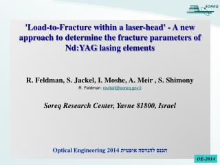
'Load-to-Fracture within a laser-head' - A new approach to determine the fracture parameters of Nd:YAG lasing elements R. Feldman, S. Jackel, I. Moshe, A. Meir , S. Shimony R. Feldman ; revitalf@soreq.gov.il Soreq Research Center, Yavne 81800, Israel

OE-2014
E N D
Presentation Transcript
'Load-to-Fracture within a laser-head' - A new approach to determine the fracture parameters of Nd:YAG lasing elements R. Feldman, S. Jackel, I. Moshe, A. Meir , S. Shimony R. Feldman; revitalf@soreq.gov.il Soreq Research Center, Yavne 81800, Israel Optical Engineeringהכנס להנדסה אופטית 2014 OE-2014
Laser gain components may fracture upon exposing to high pump power. Fracture starts at surface defects arise from manufacturing processes. To decrease fracture tendency Improve material quality. Increase component size ( decrease thermal loading). Make a tougher material (by surface treatment) Use special (composite) components. Traditional strength measurement is performed by the 4-point flexture strength (bending) technique. In the present study, however, a new technique was introduced, based on optical loading within a laser head (pumping). Introduction OE-2014
a b The problem: Fractured of large size laser rods 205 mm long Nd:YAG rods OE-2014
Fracture mechanics of brittle materials • Theoretical tensile strength EYAG= 310 GPa, • theoretical = 31,000 MPa, • actual= 133-315 MPa (single crystal) • σactual=229-378 MPa (ceramic) • Figure-of-Merit for thermal stress resistance: • Fracture mechanics relates the tensile • strength to fracture toughness, KIc using: γ – surface energy, k – thermal conductivity, n – Poisson's ratio, α – thermal expansion coefficient, E – elastic modulus a – depth of the flaw which leads to failure Y – geometry factor (about unity) KIc – fracture toughness - measure the material’s resistance to crack It is possible to improve the tensile strength of brittle materials by reducing the flaw size OE-2014
Thermal stress profiles within a laser rod 3 components of the normal stress: Temp. difference between the rod center and surface: Max. tensile stress on the rod surface: The max. stress theory (W.J.M. Rankine) OE-2014
Tensile-Strength measurement of optical materials by “load-to-fracture” • Thermal Shock: rapid water cooling of preheated specimen. • Static Temperature Gradient: by simultaneous heating and cooling. • Transient thermal shock: using a CW CO2 laser. • Mechanical bending: 3- or 4-point bending. • Thermal loading within a laser-head. First attempt to use the technique of thermal loading of a laser rod within a laser-head First attempt to use the latter technique OE-2014
Tensile-Strength measurement: Mechanical bending vs. thermal loading F Loading member y Test specimen Cylindrical bearing Support member x h b L D 2D Tensile stress on lower surface of bar Four-point fluxure test Thermal loading within a laser-head Cooling water Laser - Head Pump beam Ring-on-Ring fluxure test Four-point Concentrating lens Diode-laser array OE-2014
Weibull analysis for the strength of small Nd:YAG rods within a laser head Probability of failure • Thermal loading, Ph/l, replaces the tensile strength, . • Referring to non-fractured rods under the highest power limit as if being fractured. Maximum thermal loading of strengthened Nd:YAG laser rods: Ceramic: 320 W/cm Single crystal: > 434 W/cm OE-2014
Scaling factors obtained by Weibull analysis for poly- and single-crystalline Nd:YAG Strengthened poly-crystalline elements exhibit lower strength compared to Nd:YAG single crystal OE-2014
Defects in crystalline Nd:YAG elements Defects resulted from crystal growth process • Microscopic defects: mainly dislocations such as # Edge dislocations # Zigzag dislocations # Helices dislocations • Macroscopic defects: facets, scattering particles, bubbles, constitutional supper cooling (striations) Can be avoided by proper selection of the crystal Defects induced in laser components • Scratches, voids, foreign particles, and contaminants at the element outer faces – arise from the manufacturing process Can be avoided by careful manufacturing process Fracture of a laser component starts at defects OE-2014
After etching scratches (a) (b) (c) (d) 0.2 mm (e) (f) Non- etched etched 0.2 mm After etchingun-identified metallic spots 0.5 mm 0.5 mm 0.5 mm 0.2 mm After-etching defects • Various defects on the cylindrical surface of the laser rod could be identified after the final polishing and coating process. • In spite of our efforts, these defects could not be avoided. • In addition, an un-identified organic material penetrated into the rough surface of the rod. Such defects may lead to catastrophic damage to the laser element OE-2014
Surface absorption • “Beilby layer” • Remains of fixing / bonding materials • Micro-scratches • Surface absorption may result from – Temperature increase is proportional to the energy absorbed per unit length, causing hot-spots. • Absorption: Eabs=k·t·(As+β·l) As=2·αs·δ • A special cleaning procedure was used to removes surface contaminations. Rods have not being fractured after their final cleaning 1. N. Bloembergen, IEEE J. Quantum Electron. QE-10, pp. 375-386 (1974). 2. G. Mann, G. Phillipps, Optical Materials 4 (1995), pp. 811-814. OE-2014
Commercial fabrication process Special strengthening procedure Out-drilling of raw rods from preferred sites Fine grinding of the cylinder Thermo-chemical etching Center-less grinding Re-polishing & Re-coating Polishing Special cleaning procedure AR coating Fabrication process for enhanced laser rods OE-2014
Fracture Heat Power Density vs. Absorbed pumped power for large rods High strength of the chemically-etched Nd:YAG laser rods of full size: Thermal Loading: 125 - 200 W/cm Tensile Strength: 125 - 225 MPa . OE-2014
Weibull analysis of full-size Nd:YAG rods (ϕ8-10 x 205 mm) • Fracture: • Strengthened rods did not fracture at the highest pump power of the laser. • Rods fractured after re-polishing and re-coating • Probability of failure of full-size rod, P: • Un-treated rods: P < 45 W/cm • Strengthened rods: P > 110 W/cm Final cleaning procedure required OE-2014
(a) Probably calculated from tensile strength: Maximum pump-power density applied on single crystalline Nd:YAG laser rods 16
Summary • Unique method was developed for strength measurement of laser rods within laser heads. • This method was applied on polycrystalline (ceramics) and single crystalline laser rods. • Results indicate the reliability of the new technique. • Together with the strengthening process, the new technique enabled to demonstrate a multi-KW CW laser output from a chain of amplifiers. • It is more instructive to examine the durability of Nd:YAG laser elements by their thermal loading within a laser head, as this is the environment these components operate. OE-2014
Thanks for your attention ! R. Feldman; revitalf@soreq.gov.il