CAB, CHASSIS, AND TRAILER WIRING SYSTEMS
100 likes | 264 Vues
CAB, CHASSIS, AND TRAILER WIRING SYSTEMS. SUB-SYSTEMS. Main Cab Harness Receives power from Batteries Has Fuses and Circuit Breakers Feeds power to other truck harnesses Extends to cab/front lighting on some cab designs Some fuse panels identified well. SUB-SYSTEMS. Engine Harness

CAB, CHASSIS, AND TRAILER WIRING SYSTEMS
E N D
Presentation Transcript
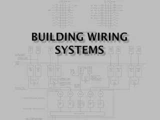
SUB-SYSTEMS • Main Cab Harness • Receives power from Batteries • Has Fuses and Circuit Breakers • Feeds power to other truck harnesses • Extends to cab/front lighting on some cab designs • Some fuse panels identified well
SUB-SYSTEMS • Engine Harness • Supplies power to starter motor, alternator, Jacob engine brake, preheating/starting system, fan clutch, shutterstats and heating and air conditioning system • Supplies power to Chassis Harness on some trucks
SUB-SYSTEMS • Chassis Harness • Supplies power to all frame mounted electrical and electronic components such as; • lighting • anti-skid brakes • fuel tank level gauge • trailer coupling connector
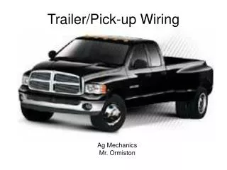
SUB-SYSTEMS • Trailer Harness • Supplies power to lighting on the trailer(s)
WIRING STANDARDS • American Manufactuers follow SAE and TMC/ATA standards • Wiring diagram supplied with every truck (affixed or pouch) • Circuit identification is standard • Wiring Colors • Standard nomenclature or abbreviations
Electrical Maps • Wiring Diagram • Grid Reference System • Pages identified by model of truck • Circuit Diagram • Shows how components are connected together without detail • Specifies location of wiring and components
CIRCUIT IDENTIFICATION • Two Methods • Color and Number • Circuit Number and Circuit Name • Letters and Numbers can be printed on wiring every 4 inches • Wiring can be tagged FIG 5-3
HARNESS STANDARDS • WIRE CONDUCTORS • ANNEALED COPPER WIRE • WIRE INSULATION • SXL - Standard duty thermosetting cross-linked polyethylene • Wiring temp must not exceed 100 degree F • If higher temp, must be protected
OTHER HARNESS STANDARDS • Voltage drop not more than 0.5V • Must be supported at least every 18 inches • Wiring Harness Coverings • Wiring should be located so that rocks, road debris, etc will not harm it.