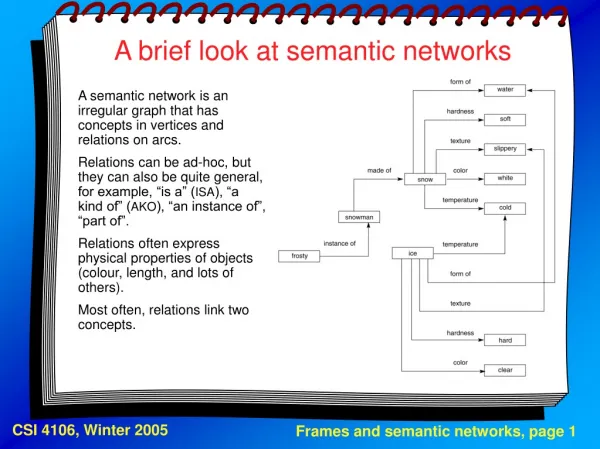
Experiment 1 Lab 4 Outline Presentation Using A Brief Look at Semiconductor Technology
1.65k likes | 1.88k Vues
Experiment 1 Lab 4 Outline Presentation Using A Brief Look at Semiconductor Technology Component selection for a new chip and a new PCB Semiconductor technology overview Gates, switches and digital electronic circuits Complementary Metal Oxide Semiconductor ( CMOS ) overview

Experiment 1 Lab 4 Outline Presentation Using A Brief Look at Semiconductor Technology
E N D
Presentation Transcript
Experiment 1 Lab 4 Outline • Presentation • Using A Brief Look at Semiconductor Technology • Component selection for a new chip and a new PCB • Semiconductor technology overview • Gates, switches and digital electronic circuits • Complementary Metal Oxide Semiconductor (CMOS) overview • Transistor-Transistor Logic (TTL) overview • Using Term Project (pages 20 - 21) • Analysis of the term project • Digital Systems • Analysis of Block 3 of the term project • Using Term Project Design Checks • Digital Design Conventions • Individual work • Experiment 1 is over three weeks : Labs 3, 4 and 5 • Develop a 4-bit 2-to-1 MUX of Block 2 • By using Handout 3 distributed in class • New handout • Term Project Design Checks CS 2204 Spring 2014
What are these components ? Today’s work • Presentation • Xilinx Project Development Steps • Develop the schematic • Design the schematic • Place the components and wires • Do a schematic check • Test the schematic via logicsimulations • Do a Xilinx IMPLEMENTATION • It maps the components to the CLBs of the chip • Do timing simulations to test the schematic • It generates the bit file • Download the bit file to the FPGA and test the design on the board • It programs the chip CS 2204 Spring 2014
Developing a digital product • A new chip • Which gates & FFs and how many is determined by • Available components of technology chosen • Besides the major operations and speed, cost, power, etc. design goals of the digital product • FPGAs are used to test the new chip • A new PCB • Which chips and how many is determined by • Available chips of technology chosen • Besides the major operations and speed, cost, power, etc. design goals of the digital product CS 2204 Spring 2014
Developing a digital product • A new chip • We will try to use high density components as much as possible • We will try not to use low-density components (gates and flip-flops) • We will work on chip design in the classroom and in the lab • Lectures, homework assignments, exams andlabs CS 2204 Spring 2014
Use these as much as possible • CS2204 Components • Available components for a new chip Generic components Lectures, homework, exams Xilinx components Labs Flip-flops Gates Popular digital circuits Gates Flip-flops Popular digital circuits ADDer Comparator Multiplexer DeMux Decoder Encoder ALU Counter Register … ADDer Comparator Multiplexer DeMux Decoder Encoder ALU Counter Register … AND OR NOT NAND NOR … D JK T SR … AND OR NOT NAND NOR … D T JK High-density components To save time, space, power. weight,… CS 2204 Spring 2014
Lab design Use Xilinx macros as much as possible Try not to use these components • CS2204 Components • Available components for a new chip Xilinx components Labs Generic components Lectures, homework, exams Gates Flip-flops Popular digital circuits Gates Flip-flops Popular digital circuits ADDer Comparator Multiplexer DeMux Decoder Encoder ALU Counter Register … D T JK AND OR NOT NAND NOR … AND OR NOT NAND NOR … D JK T SR ADDer Comparator Multiplexer DeMux Decoder Encoder ALU Counter Register … High-density components CS 2204 Spring 2014
Developing a digital product • A new PCB • We will try to use high density chips (MSI, LSI, VLSI, ULSI) as much as possible • We will try not to use low-density chips (SSI) • We will work on PCB design in the classroom • Lectures,homework assignments andexams CS 2204 Spring 2014
Use these as much as possible • CS2204 components • Available chips for a new PCB Generic chips Lectures, homework, exams TTL LS chips Lectures, homework, exams Gates Flip-flops Popular digital circuits Flip-flops Gates Popular digital circuits AND OR NOT NAND NOR … D JK T SR … ADDer Comparator Multiplexer DeMux Decoder Encoder ALU Counter Register … AND OR NOT NAND NOR … ADDer Comparator Multiplexer DeMux Decoder Encoder ALU Counter Register … D JK High-density chips To save time, space, power. weight,… CS 2204 Spring 2014
Use higher density chips (MSI, LSI,…) as much as possible Try not to use these SSI chips • CS2204 components • Available chips for a new PCB TTL LS chips Lectures, homework, exams Generic chips Lectures, homework, exams Flip-flops Gates Popular digital circuits Gates Flip-flops Popular digital circuits AND OR NOT NAND NOR … ADDer Comparator Multiplexer DeMux Decoder Encoder ALU Counter Register … D JK ADDer Comparator Multiplexer DeMux Decoder Encoder ALU Counter Register … AND OR NOT NAND NOR … D JK T SR … MSI, LSI chips High-density chips CS 2204 Spring 2014
D FF implementation via gates D FF From ON Semiconductor LS TTL Data Manual • Digital circuits consist of gates and FFs • FFs consist of gates • Digital circuits consist of gates ! • Gates are on chips ! • Chips are on PCBs CS 2204 Spring 2014
Gates are implemented by electronic components : Transistors, resistors, diodes, capacitors,… TTL2-input NAND gate implementation via electronic components NAND 74LS00 Quad 2-input TTL NAND Gate chip From ON Semiconductor LS TTL Data Manual CMOS 2-input NAND gate implementation via electronic components CS 2204 Spring 2014
TTL 2-input NAND gate ON Semiconductor LS TTL Data Manual • Most Common Voltages for Logic Values • Logic 1 is +5v • Logic 0 is 0v • The terminology • +5v VCC • 0v GND (Ground) • Xilinx Devices for voltages VCC and GND are on the Xilinx component list CMOS 2-input NAND gate implementation via electronic components 2-input NAND gate CS 2204 Spring 2014
0 1 0 1 1 1 • Transistors are the Main Electronic Component • Transistors are used as switches to implement gates • A switch is open or closed based on the control input value : • Open when control is 0 : • Closed when control is 1 • The speed of switches determines the speed of the electronic circuit, therefore, the gate CS 2204 Spring 2014
k m k k.m 1 k.m 1 AND m AND gate • Implementing AND gates • Implemented by twoswitches connected in series CS 2204 Spring 2014
k k 1 k + m k + m OR m m OR gate • Implementing OR gates • Implemented by twoswitches connected in parallel CS 2204 Spring 2014
k k k NOT 1 1 NOT gate (inverter) • Implementing NOT gates • Implemented by oneswitch CS 2204 Spring 2014
a b 1 a c a NOT AND b A switching network implementing a gate network OR a AND c y(a, b, c) =a.b + a.c y(a, b, c) =a.b + a.c • 2-to-1 MUX Implementation CS 2204 Spring 2014
The Gate Implementation Implementing gates is morecomplex than just connecting switches (transistors) in series/parallel A 2-input NAND gate implementation Resistors, diodes, etc. are used for reliable operation with TTL technology Five transistors : Q1 – Q5, six diodes : D1 – D6 and seven resistors Multiple transistors are used for reliable operation with CMOS technology A 2-input NAND gate implementation Four transistors NAND CMOS 2-input NAND gate implementation via electronic components TTL 2-input NAND gate ON Semiconductor LS TTL Data Manual CS 2204 Spring 2014
Thedieof chip : area containing transistors, resistors, diodes,… Die There are more than225 milliontransistorsondie A chip www.intel.com Intel Pentium 4die • Electronic Components on the Chip • All electronic components are placed in the die area CS 2204 Spring 2014
Die Intel Pentium 4 chip IntelPentium 4die IntelPentium4wafer • Die Fabrication Today • Dice for the same chip type are placed on a wafer From : Intel CS 2204 Spring 2014
Gates have features • Speed, Cost, Power, Size,… • Transistors, resistors,.. have features (devicecharacteristics) • Speed, cost, power, size,.. • Device characteristics are determined by • The substance used for chips • Silicon, Silicon Germanium, Gallium Arsenide • The transistor type • Unipolar, bipolar • Electronic (transistor) circuits that form the gates • CMOS, BiCMOS, TTL, ECL,… Technologies CS 2204 Spring 2014
In order to study gatefeatures • Speed, Cost, Power, Size,… • We need to study substances, transistor types and transistor circuits • The technology chosen • CMOS, BiCMOS, TTL, ECL • They have their own subfamilies CMOS : HC, HCT, AC, ACT, FCT,… TTL : H, L, S, LS, AS,… CS 2204 Spring 2014
Substances Today’s chips use semiconductor substances Silicon is the most common semiconductor substance Silicon is the slowest substance Transistorswere implemented by germanium, asemiconductor Transistorsarenowimplemented by silicon, anothersemiconductor CS 2204 Spring 2014
Transistors Unipolar transistors are slower, but consume less power CS 2204 Spring 2014
Transistors Circuits CMOS circuits are slower, but consume less power Microprocessor chips are CMOS TTL chips are the most widely available GPU chips are CMOS DRAM chips are CMOS FPGA chips are CMOS More on gate features next week ! CS 2204 Spring 2014
b) c) d) e) • Today : BeyondULSI Multi- chip module, MCM (>1 die on chip), Giga Scale, etc. (200M–7B transistors) • Silicon Technology Today a) IntelPoulson(Itanium) 8 cores 32 Mbyte L3 Cache 3.1 Billion transistors, 170Watts Will there be an end to shrinking the silicon transistor size ? CS 2204 Spring 2014
Fan-in • The maximum number of inputs a gate can have • This is purely electrical • Determined by the technology • The electronic circuitry determines how many inputs to have for reliable operation CS 2204 Spring 2014
Fan-out • The number of gate inputsthat can be connected to a gate output • This is purelyelectrical • Determined by the technology • CMOS gates have the best fan-out • If the fan-out is exceeded • The output value may be noisy • The output value may not be electrically “strong” to be interpreted as 1 or 0 • The output can be physically damaged CS 2204 Spring 2014
Fan-out • In order to increase the fan-outbuffers are used • Regular buffers (not input nor output buffers) are used to increase the fan-out • A buffer is an electronic circuit that has no logic function ! • It transfers the input to the output with a delay ! • It also strengthensthe electrical signal • Some buffers are also labeled as drivers since they can electrically “drive” large currents, hence drive many inputs • Some buffers are designed so that they can filter noise on the inputs CS 2204 Spring 2014
y b Use a buffer ! But, the input to output delay is increased ..... a c ..... • Fan-out • Increasing the fan-out CS 2204 Spring 2014
Technology of components/chips • Complementary Metal Oxide Semiconductor (CMOS) • Uses unipolar transistors • Slower than Bipolar transistors • Consume less power than Bipolar transistors • Not straightforward to connect to TTL chips CS 2204 Spring 2014
Complementary Metal Oxide Semiconductor (CMOS) • Low densitycommercial CMOS families, each with a different combination of speed, power, cost • 4000 (Oldest) • 74HC (High speed CMOS) • 74HCT (High speed CMOS, TTL Compatible) • 74AC (Advanced CMOS) • 74ACT (Advanced CMOS, TTL Compatible) • 74FCT (Fast CMOS, TTL Compatible) • 74FCT-T (Fast CMOS, TTL Compatible with TTL VOH) • Most high-density chips • Microprocessors, GPUs, FPGAs, DRAMs, Flash-EPROMs,.. CS 2204 Spring 2014
Complementary Metal Oxide Semiconductor (CMOS) • CMOS chips consume very little power • Better Fan-out than TTL chips • CMOS chips are sensitive to staticelectricity • One should nottouch them • Unless properly grounded • A wire strappedaround the wrist is connected to the ground • The ground has 0v CS 2204 Spring 2014
a a • Complementary Metal Oxide Semiconductor (CMOS) • Unused gate input • Do not leave it unconnected (floating) • Xilinx does not allow this option ! • A No Driver warning is given by the Project Manager ? y y b b The gate will not work properly Hi-Z value observed at the input CS 2204 Spring 2014
U4 y • Digital Engineering Terminology U1 U2 a Must be corrected b U4 input has no driver U4 input is not connected to an output. Its input value is Hi-Z (High-Impedance) as there is infinite impedance (resistance) into the U4 input so no current can flow in a c U3 CS 2204 Spring 2014
y b a • Complementary Metal Oxide Semiconductor (CMOS) • Unused gate input • It can be tied to a used input • The fan-out of the b signal may be exceeded ! An available 3-input AND gate used to implement a 2-input AND gate CS 2204 Spring 2014
y b y b a a Pull-down resistor Pull-up resistor 0 v +5 v • Complementary Metal Oxide Semiconductor (CMOS) • Unused gate input • It can be connected to 1 or 0 depending on the gate type, via a pull-up resistor or pull-down resistor CS 2204 Spring 2014
Xilinxwarning message from the Project Manager : Multiple drivers on output y • Complementary Metal Oxide Semiconductor (CMOS) • Gate output • Regular Donot shortcircuit regular gate outputs y CS 2204 Spring 2014
U4 y • Digital Engineering Terminology U1 U2 a b a c Must be corrected U3 Multiple drivers on output y U3 and U4 outputs are short circuited CS 2204 Spring 2014
Enable y y Operation table 0 Hi-Z b a 1 ab Tri-state symbol Enable • Complementary Metal Oxide Semiconductor (CMOS) • Gate output • Tri-state outputs • The output has three values ! • 1,0and Hi-Z≡ High-impedance ≡ Floating≡ Static voltage • There is an extra control input, Enable, to enable/disable output ► If disabled, the output value is Hi-Z (high-impedance) CS 2204 Spring 2014
y y b b a a Enable Regular gate • Complementary Metal Oxide Semiconductor (CMOS) • Gate output • Tri-state outputs • A tri-state gate can be envisioned as a regular gate with a switch at the output Output y has three values Enable Switch closed Switch open 0 1 Hi-Z CS 2204 Spring 2014
Enable1 You canshort circuit tri-state gate outputs A bus line Enable2 • Complementary Metal Oxide Semiconductor (CMOS) • Gate output : • Tri-state gate outputs can be short circuited if only one gate isenabledat a time Tri-state outputs are often used to implement buses y CS 2204 Spring 2014
y b Pull-up resistor Open drain symbol a +5 v • Complementary Metal Oxide Semiconductor (CMOS) • Gate output : • Open-drain • An external pull-up resistor is needed • Open-drain outputs are often used • To drive displays and lights • To implement buses CS 2204 Spring 2014
You canshort circuit open-drain gate outputs A bus line +5 v +5 v • Complementary Metal Oxide Semiconductor (CMOS) • Gate output : • Open-drain • Gate outputs can be short circuited CS 2204 Spring 2014
Technology of components/chips • Transistor-Transistor Logic (TTL) • Uses bipolar transistors • Consists of two sets of families • Commercial : 74xxxx • Cheaper • Widely available • Military : 54xxxx • Manufactured for more stringent applications • Expensive CS 2204 Spring 2014
We will use it from time to time • Transistor-Transistor Logic (TTL) • Low density commercial TTL families, each with a different combination of speed, power, cost,.. • 74 (Standard) • 74L (Low-power) • 74S (Schottky) • 74LS (Low-power Schottky) • 74H (High speed) • 74AS (Advanced Schottky) • 74ALS (Advanced Low-power Schottky) • 74F (Fast) CS 2204 Spring 2014
Implemented by an available 3-input AND gate y y b b a a NAND TTL 2-input NAND gate ON Semiconductor LS TTL Data Manual NAND gate • Transistor-Transistor Logic (TTL) • Unused gate input • It can be leftunconnected (floating) • It can be confusing • If the designer leaves the company and a new engineer works on the circuit it can be confusing especially if the documentation is not good ! CS 2204 Spring 2014
y b a • Transistor-Transistor Logic (TTL) • Unused gate input • It can be tied to a used input • The fan-out of the b signal can be exceeded An available 3-input AND gate used to implement a 2-input AND gate CS 2204 Spring 2014
y b y b a a Pull-down resistor Pull-up resistor 0 v +5 v • Transistor-Transistor Logic (TTL) • Unused gate input • It can be connected to 1 or 0 depending on the gate type, via a pull-up resistor or pull-down resistor CS 2204 Spring 2014