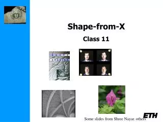
Shape from X
CS 636 Computer Vision. Shape from X. Nathan Jacobs. Slides by Lazebnik. Cues to 3D. Motion Shading Defocus (moving) Shadows and Specularities Texture. Photometric Stereo. Merle Norman Cosmetics, Los Angeles. Readings

Shape from X
E N D
Presentation Transcript
CS 636 Computer Vision Shape from X Nathan Jacobs Slides by Lazebnik
Cues to 3D • Motion • Shading • Defocus • (moving) Shadows and Specularities • Texture
Photometric Stereo Merle Norman Cosmetics, Los Angeles • Readings • R. Woodham, Photometric Method for Determining Surface Orientation from Multiple Images. Optical Engineering 19(1)139-144 (1980). (PDF) Slides by Seitz
image intensity of P Diffuse reflection • Simplifying assumptions • I = Re: camera response function f is the identity function: • can always achieve this in practice by solving for f and applying f -1 to each pixel in the image • Ri = 1: light source intensity is 1 • can achieve this by dividing each pixel in the image by Ri
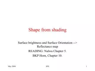
Shape from shading • Suppose • You can directly measure angle between normal and light source • Not quite enough information to compute surface shape • But can be if you add some additional info, for example • assume a few of the normals are known (e.g., along silhouette) • constraints on neighboring normals—“integrability” • smoothness • Hard to get it to work well in practice • plus, how many real objects have constant albedo?
L3 L2 L1 Photometric stereo N V Can write this as a matrix equation:
Least squares solution: Solve for N, kd as before What’s the size of LLT? More than three lights • Get better results by using more lights
Computing light source directions • Trick: place a chrome sphere in the scene • the location of the highlight tells you where the light source is
V2 V1 N Depth from normals • Get a similar equation for V2 • Each normal gives us two linear constraints on z • compute z values by solving a matrix equation orthographic projection
Results… Input (1 of 12) Normals Normals Shadedrendering Texturedrendering
Results… from Athos Georghiades http://cvc.yale.edu/people/Athos.html
Limitations • Big problems • doesn’t work for shiny things, semi-translucent things • shadows, inter-reflections • Smaller problems • camera and lights have to be distant • calibration requirements • measure light source directions, intensities • camera response function • Newer work addresses some of these issues • Some pointers for further reading: • Zickler, Belhumeur, and Kriegman, "Helmholtz Stereopsis: Exploiting Reciprocity for Surface Reconstruction." IJCV, Vol. 49 No. 2/3, pp 215-227. • Hertzmann & Seitz, “Example-Based Photometric Stereo: Shape Reconstruction with General, Varying BRDFs.” IEEE Trans. PAMI 2005
Many Methods • Try many focal depths, pick the sharpest for each pixel • Treat circle of confusion like a local blur… use a deconvolution method. • (more on that)
Image and Depth from a Conventional Camera with a Coded Aperture Anat Levin, Rob Fergus, Frédo Durand, William Freeman MIT CSAIL
Output #1: Depth map Single input image:
Output #1: Depth map Single input image: Output #2: All-focused image
Lens and defocus Image of a point light source Lens’ aperture Camera sensor Lens Point spread function Focal plane
Lens and defocus Image of a defocused point light source Lens’ aperture Camera sensor Object Lens Point spread function Focal plane
Lens and defocus Image of a defocused point light source Lens’ aperture Camera sensor Object Lens Point spread function Focal plane
Lens and defocus Image of a defocused point light source Lens’ aperture Camera sensor Object Lens Point spread function Focal plane
Lens and defocus Image of a defocused point light source Lens’ aperture Camera sensor Object Lens Point spread function Focal plane
Out of focus In focus Depth and defocus Depth from defocus: Infer depth by analyzing local scale of defocus blur ill posed
Challenges • Hard to discriminate a smooth scene from defocus blur • Hard to undo defocus blur ? Out of focus Input Ringing with conventional deblurring algorithm
Defocus as local convolution Calibrated blur kernels at different depths Input defocused image
Defocus as local convolution Local sub-window Calibrated blur kernels at depth Sharp sub-window Input defocused image Depth k=1: Depth k=2: Depth k=3:
Overview Try deconvolving local input windows with different scaled filters: ? Larger scale ? Correct scale ? Smaller scale Somehow: select best scale.
? Larger scale ? Correct scale ? Smaller scale Challenges • Hard to deconvolve even when kernel is known • Hard to deconvolve even when kernel is known Input Ringing with the traditional Richardson-Lucy deconvolution algorithm • Hard to identify correct scale:
Deconvolution is ill posed Solution 1: = ? Solution 2: = ?
Idea 1: Natural images prior What makes images special? Natural Unnatural Image gradient Natural images have sparse gradients put a penalty on gradients
Deconvolution with prior Convolution error Derivatives prior 2 _ + ? Low Equal convolution error 2 _ + ? High
“spread” gradients “localizes” gradients Richardson-Lucy Gaussian prior Sparse prior Comparing deconvolution algorithms (Non blind) deconvolution code available online: http://groups.csail.mit.edu/graphics/CodedAperture/ Input
Comparing deconvolution algorithms (Non blind) deconvolution code available online: http://groups.csail.mit.edu/graphics/CodedAperture/ Input “spread” gradients “localizes” gradients Richardson-Lucy Gaussian prior Sparse prior
Recall: Overview Try deconvolving local input windows with different scaled filters: ? Larger scale ? Correct scale ? Smaller scale Somehow: select best scale. Challenge: smaller scale not so different than correct
Depth from Diffusion Changyin Zhou Oliver Cossairt Shree Nayar Columbia University Supported by ONR
Optical Diffuser ~ 10 micron Micrograph of a Holographic Diffuser (RPC Photonics) [Gray, 1978] [Chang et al., 2006] [Garcia-Guerrero et al. 2007]
Diffuser to preview the image (B&H) Diffusers for illumination (B&H) Diffusers to soften the image Diffusers as Accessories
Object Object Diffuser Camera Diffuser Camera Diffusion Encodes Depth The amount of diffusion varies with depth.
Geometry of Diffusion: A Pinhole Camera Object P Miss Pinhole Q Sensor
θ Geometry of Diffusion: A Pinhole Camera Object P Pinhole Sensor Diffuser
A θ B θ Geometry of Diffusion: A Pinhole Camera Object P Pinhole Sensor Diffuser
Geometry of Diffusion: A Pinhole Camera Diffusion Law: Object A P θ B θ Pinhole O 2r V Z U Sensor Diffuser Object
Geometry of Diffusion: A Pinhole Camera Diffusion Size and Depth: Object A P θ B θ Pinhole O 2r V Z U Sensor Diffuser Object
Geometry of Diffusion: A Pinhole Camera Diffuser as a proxy object Diffusion Size and Depth: Z P Pinhole O 2r V U Sensor Diffuser Object
Captured Image Diffusion PSF Latent clear image Diffusion Size Diffusion as Convolution: A Pinhole Camera Assume field angle and depth are constant for small image patches, we have:
Experiments Canon 20D + 50mm Lens Five playing cards, 0.29mm thick each Luminit Diffuser (20o)
Experiments Captured WITHOUT a Diffuser Captured WITH a Diffuser