Download
1 / 34
631 likes | 1.65k Vues
LIQUID CRYSTALS Introduction. LC mesophases LCs in the bulk and in confined geometries optical properties of LCs fluctuations and light scattering applications of LCs. AG GREGATION STA TES OF MATTER. heating. cooling. Example : H 2 O molekule. Liquid phase.

E N D
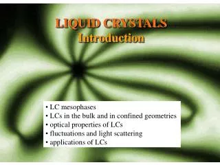
LIQUID CRYSTALS Introduction • LC mesophases • LCs in the bulk and in confined geometries • optical properties of LCs • fluctuations and light scattering • applications of LCs
AGGREGATION STATES OF MATTER heating cooling Example: H2Omolekule Liquid phase Solid phase (crystal)
THERMOTROPICLIQUID CRYSTALS heating cooling Solid phase (crystal) Liquid crytalline phase Liquid phase Rod-like molecules (calamatic LCs) example: alkhyl-cianobiphenyls Disc-shape molecules (discotic LCs) example: triphenylene derivatives Texture of the LC phase observed by polarization optical microscopy Synthetic materials
LIOTROPIC LIQUID CRYSTALS decreasing concentration increasing concentration Molecular solutions Solid phase (crystal) Liquid phase Liquid crystalline phase Examples: soaps, lipids, viruses, DNA... Natural materials 100 nm TM virus
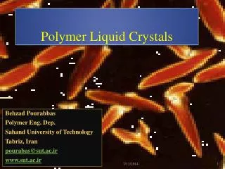
POLYMER LIQUID CRYSTALS main chain polymer LCs side chain polymer LCs Examples: Kevlar (du Pont), solutions of biopolymers Kevlar
GENERAL PROPERTIES OF LC-MESOPHASES • They flow and form surface level • (similar to liquids) 2) They exhibit anisotropic material properties (similar to crystals) Example: opticalbirefringence n1 n2 3) In some cases they can transmitt mechanical stress (similar to crystals) Example: bend strain
THERMOTROPIC LIQUID CRYSTAL PHASES of achiral molecules • Parameters describing the liquid crystalline phase: • Orientational order • Positional order • Bond orientational order nematic phase (N) smectic A phase (SmA) smectic C phase (SmC) columnar phase (2D lattice)
NEMATIC LC PHASE – theoretical description Basic thermodynamic argument for the I-N phase transition: Although orientational alignment of the molecules results in the loss of the entropy S, this loss is compensated by a decrease of the interaction energy U(because Van der Waals attractive forces are increased, molecular packing is optimized, ...) F = U – TS Microscopic description: f() angular distribution function f()d = fraction of the molecules pointing into a solid angle head to tail invariance of the nematic phase requires f()=f(-)!! nematic order paramer SN = <((3cos2)-1)/2> = Isotropic phase: SN = 0, totally aligned N phase SN = 1. Maier-Saupe theory: U= –u SN2 , ˆ n=director
NEMATIC - ISOTROPIC PHASE TRANSITION SN can be measured via anisotropy of the material properties. example: diamagnetic susceptibility z= n(II<cos2>+ <sin2>) = n(+(2/3)aSN) x= y = n(–(1/3)aSN) SN=(z–x)/(na) z where molecular parameters =(II+2)/3, a= (II-), n=N/V x y should be known from other measurements.
ELASTIC DEFORMATIONS IN NEMATICS Nematic phase can transmit forces in cases in which the corresponding deformation perturbs the long-range orientational order. F F For example: shear stress will produce usual viscous liquid flow, whilesplay,twistandbend deformations will produce elastic response. Elastic energy density of distortion (continuum theory): Frank elastic constants: Ki 10-12 N
EFFECT OF INTERFACE INTERACTIONS Nematic phase between two planar surfaces. Surface forces generally induce bulk aligment in some preferential direction (easy axis). • = angle between n and the easy axis Fsurface=f0+Bsin2 ^ ^ n easyaxis Rapini-Papoular approximation Surface anchoring energy coefficients: BB10-5N/m Nematic phase cofined to spherical droplets. F=Fsurface+Fd=MIN Approximation of infinitely strong anchoring (B=) is often reasonable.
STANDARD TECHNIQUE TO ACHIEVE PLANAR SURFACE ANCHORING LC Polyimide glass glass Unidirectional rubbing Polymer surface is melted due to applied force and melted polymer molecules align in the direction of the rubbing. glass
ALIGNMENT OF LIQUID CRYSTALS ON RUBBED POLYMER SURFACE Anisotropicinteraction between the polymer substrateand the rod-shape liquid crystal molecules inducesorientationalordering of the LC layer. 1 mm Nematic LC texture in a cell without and with the alignment layer.
EFFECT OF EXTERNAL FIELDS Due to head-tail invariance of the molecular arrangement, the nematic phase has no spontaneous macroscopic electric polarization P and magnetization M. External electric and magnetic fields produce induced polarization/magnetization (P=0eE, M=mH). For dielectric polarization local field corrections are quite important!! z Pz= on(+(2/3) aSN)fhEz=o( II-1) Ez Px= on(–(1/3) aSN) fhEx=o( -1) Ex x y h=3 /(2 +1) cavity field factor f reaction field factor • , 0 , 0 0 , , 0 0 , 0 , II ^ = Dielectric tensor in case of zIIn: ^ in general: = 1+ a(nn), where a=( II- ) is dielectric anisotropy. ^ ^ ^ D= o(E+a(n·E)n)
DIELECTRIC ANISOTROPY (T) DSC 60 50 70 20 30 40 Temperature dependence of the dielectric constant and the DSC response of the liquid crystal 5CB.
FREEDERICKSZ EFFECT Electrostatic free energy density: ^ For a>0 electric field tends to align the LC director n along the field direction. In confined geometries this tendency is opposed by surface anchoring. Competition results in the threshold behaviour.Example: nematic cell with planar anchoring: z U U + + – – x E>Eth E<Eth ^ Reorientation:n=n0+n(z), n0=ex,, nIIez, approximation:n(z)= (n)sin(z/d) Total free energy density: Ft=Fe+Fd= critical field ~ 1V/m
THERMOTROPIC LIQUID CRYSTAL PHASES of chiral molecules Via intramolecular interactions chiralityis transmitted from the microscopic to the macroscopic scale. Chiral nematic phase (N*), known also as cholesteric phase (Ch) Spontaneously twisted Chiral smectic A phase (SmA*) Similar to achiral SmA, but exhibits optical activity p/2 Chiral smectic C phase (SmC*) Tilted and spontaneously twisted (exhibits ferroelectricity)
Example: LC phases of DNA in aqueous solutions spherulite of thecholestericphase c>10 wt % segment of DNA hexagonal LC phase
OPTICAL PROPERTIES OF THE NEMATIC PHASE = 1+a(nn), a=( –)=nSN( – )fh Dielectric tensor at optical frequencies (~1015 Hz), refractive index n=()1/2 n-n = n 0.2 LC phases have very large birefringence: Optical axis is parallel to the nematic directorn. ^ ^ n birefringent medium k=(/c)n ^ n Ordinary beam: no= n (k/k) Extraordinary beam: sE ordinary polarization extraordinary polarization
OPTICAL BIREFRINGENCE Nematic liquid crystals are strongly birefringent “liquids”!!! N I (ne-no) SN F=(2p(n)d)/l Phase retardation between ordinary and extraordinary ray in d=4l thick LC layer is 2p !!! Phase retardation can be mediated by relatively low external voltages (Freedericksz effect). Liquid crystal have large electrooptic response!!!
COLORFULL NEMATIC TEXTURES observed between crossed polarizers Phase retardation between ordinary and extraordinary ray F=(2p(n)d)/l depends on local orientation of the director field n(r) ^ Optical polarization microscopy: Polariser Analyser Transmittance T = T (F)
OPTICAL PROPERTIES OF THE CHOLESTERIC PHASE Spatial periodicity (pitch p) of the director field n(r) is typically in the range of optical wavelengths. ^ n(z)=(cos(qz), sin(qz), 0) /2 q=2/p z x Dielectric tensor in x,y plane: ^ ^ = 1+a(nn) = a+bcos(2qz), bsin(2qz) bsin(2qz), a-bcos(2qz) a=(+)/2, b=(-)/2 Spiralling index ellipsoid. (Analytical solutions of WE for kIIz andd=) ImK means strong selective reflection for ~p. Cholesteric LCs are natural 1D photonic band-gap media !!
SELECTIVE REFLECTION and MAUGUIN LIMIT • For ~p circularly polarized beam which matches the chirality of the structure is totally reflected. The width of the reflection (forbidden) band ~n·p. Theory versus practice. • For << p the polarization plane of the linearly polarized light is rotated synchro-nously with the spontaneous twist of the structure (Mauguin limit). The material acts as a strongly optically active medium.
LIGHT SCATTERING IN THE NEMATIC PHASE One of the most profound optical manifestations of the thermal fluctuations. n(r)=n(q)eiqr n(r)=n0(r)+n(r) d Fluctuations of the director field n(r) produce increase of the elastic energy Fd 2 2 Fd=(V/2)n1(q)(K1q2+K3q2)+n2(q)(K2q2+K3q2) q kT kT Ki 10-12 N Overdamped relaxation: n0 n dFd/dni=-ini/t, i=1,2 1 q 2 n(q,t)=n(q,0)e-t/ Relaxation rate: (1/)(K/)q2 10-5cm2/s 10-6 –1 s
EKSPERIMENTAL ANALYSIS Photon correlation spectroscopy (known as PCS or DLS): probing range 10-9 –103 s Largest scattering cross section for n(q= qs) . sample Laser transmitted light H scattered light V Detector (I(t)|Es(t) |2) we measure g(2)(t)=<I(t’)I(t’+t)>/<I>2 DLS provides information on of different fluctuation modes n(q,t). This gives the values of (Ki/) for different types of deformations.
LIGHT SCATTERING FROM CONFINED LC STRUCTURES • Spherical LC droplets of radius R • qmin/R, (1/)min(K/)R-2 qmin/D, (1/)min(K/)D-2 B) Thin LC film of thickness D ~. ? s DLS gives information on cavity size (R or D) and surface anchoring koefficient B.
APPLICATIONS OF LIQUID CRYSTALS Most important comercial products based on LCs are LCDs. Present top LCD: WUXGA (wide ultra extended graphics array) 1920 x 1200 pixels. • Other applications: • optical switching devices, • optical filters, • temperature and stress sensors, • special paints and colorants, • cosmetics, • etc.
Liquid Crystal Display (LCD) PRINCIPLE Polariser Polariser Electrodes Voltage ON Analyser Analyser No output light Polarized output light Picture element is white Picture element is black
FROM PICTURE ELEMENT to THE DISPLAY Segment-type display Active matrix display composition of TFT LCD colour filter (RGB) colours polariser liquid crystal material semiconductor platform skupna elektroda common electrode segment electrode skupna elektroda backlight
SWITCHABLE WINDOWS voltage on voltage off Switchable windows are made from polymer dispersed liquid crystals (PDLC)
OTHER APPLICATIONS Car paint from chiral LCs. Temperature sensor from cholesteric LCs LCs in ART: Art-painting made by use of the polysiloxaneLC paint. left: inreflected light right: in transmitted light