Download
1 / 19
500 likes | 2.96k Vues
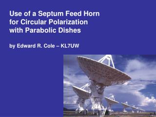
Use of a Septum Feed Horn for Circular Polarization with Parabolic Dishes by Edward R. Cole – KL7UW. Credits: This paper provides a brief compendium of papers addressing the application of the Septum Polarizer to Amateur Radio antennas.

E N D
Use of a Septum Feed Hornfor Circular Polarizationwith Parabolic Dishesby Edward R. Cole – KL7UW
Credits: This paper provides a brief compendium of papers addressing the application of the Septum Polarizer to Amateur Radio antennas. Special Thanks to Zdenek Samek and Paul Wade for permission to re-use certain figures and tables from their papers. Feed horn design for parabolic dishes has long been the focus for many microwave engineers. Add the desire to incorporate circular polarization and design can get complicated. Amateur Radio Astronomers have few feeds to chose from. For Linear Polarization: - dipole with reflector - open waveguide - pyramidal horn - waveguide with coax probe Overview
For Circular Polarization: - axial-mode helix (helical beam) - crossed dipoles - orthogonal probes in waveguide using a hybrid There are slow wave methods: - dielectric slabs - posts at 45-degrees inside waveguide - asymmetric waveguide (squeeze tube) - septum Many beginning radio astronomers have used the helical beam, but it is limited to one sense of circular polarization. The helix does not produce the nicest illumination of the dish, with resulting edge spillover and high side lobe energy. This degrades system noise temperature. The use of dishes by Amateur Radio for EME (Moonbounce) shares many of these problems. Overview
Overview • One of the most popular EME feed horns has been the “VE4MA” Feed. • It is a section of circular waveguide with orthogonal coax probes. • The Quadrature Hybrid that is required with this feed introduces loss ahead of the LNA which degrades noise temperature. • Zdenek Samek – OK1DFC introduced the Septum feed at the 2002 Int’l EME Conference in Prague.
What is a Septum Feed Horn • Four functions of feed horns: - Antenna Section: shapes beam for good illumination. - Waveguide Section - Polarizer - Excitation Section: waveguide or coaxial probe. • Chen and Tsandoulas wrote of their exploration of the septum polarizer (IEEE, 1973). Their’s was an empirical study to find a design solution. • Their design utilized a square waveguide with metal divider (or septum) separating this into two rectangular waveguide sections.
Analysis • The septum divides the excitation region into two rectangular waveguides where linear polarization exists. • The size of the waveguide is chosen to be near the cutoff frequency so that as a signal enters the horn only one polarization component is passed into the rectangular sections. • Thus one side receives RHCP and the other LHCP. • Wave cancellation in the opposite sides offer considerable isolation of the coaxial ports. • Detailed description can be found in the referenced papers listed in the footnotes.
Analysis • A sloped septum was found to be usable over only a 10% band width (though isolation was near 40 dB). Trial and error led to a stepped design with 25% band width, 24 dB isolation, and 21 dB of circularity. • Zdenek scaled Chen & Tsandoulas’ five step septum to 1296 MHz and later to other microwave frequencies.
Practical Designs • I used Zdenek’s online calculator to produce dimensions for 1420 MHz as shown in Appendix-A • Paul Wade, W1GHZ, has made a thorough analysis of the septum feed using Ansoft ANSS software. • He found that the square septum design has large rear lobes in the antenna pattern. They are only ten dB down from the main beam resulting in degrading antenna efficiency (60%) with higher noise temperature.
Practical Designs • Since side lobes are generated in the opening of the feed horn the addition of a flared horn improves side lobes with dishes of 0.5 to 0.7 F/D ratio. • Efficiencies of 65 to 70% are achieved. • A round choke ring is most effective reducing side lobes with dishes of 0.3 to 0.45 F/D ratio. • Efficiencies of 62% are achieved.
Super – VE4MA Feed Horn • This year Paul investigated use of the stepped septum in circular fed horns. • In the process he found increased efficiencies using deeper choke rings with a 0.77 wavelength diameter horn. • Increasing ring dimensions to 0.4 by 0.6 wavelength, analysis showed theoretical efficiencies to 80% with low side lobes. • Measurements of this horn by Tommy Henderson, WD5AGO, measured actual 65% efficiency!
KL7UW Septum Feed • Here is the Square Septum Feed that I built in fall 2005 and mounted on my 2.4 meter dish. • Operation over 1296 to 1420 MHz with good return-loss and isolation. • Sun noise Measurements produced 4-dB comparison with cold sky. • Cold Sky vs. Ground noise with the feed horn measured 4.5 dB without a choke ring and 7 dB with a ring. • Wide band noise measurements this spring were not successful due to microwave front-end problems.
Radio Astronomy Application • The Septum Feed Horn provides a much simpler and efficient way to make multi-polarity radio astronomy observations. • Both RHCP and LHCP may simultaneously be observed using matched LNA’s on both ports of the septum feed. • Addition of two-way signal splitters and a quadrature hybrid, orthogonal linear polarity can be recovered. • Improved System Noise Temperature. • Dual frequency observations over 25% separation. • Normal radio telescope antenna efficiency is 40-45% in the effort to minimize side lobes below 20 dB. • The cylindrical stepped-septum feed provides 65% efficiencies. This is equivalent to a 20% increase in effective antenna aperture!