Download
1 / 10
100 likes | 123 Vues
Implement a dynamic architecture for signal flow in an OpenGL application with detailed controllers, modules, interfaces, and coordinate spaces. Utilize key tools and widgets for user interaction and data manipulation. Explore the structure of worlds, interfaces, and data organization within a rendering environment.

E N D
Signal Flow OpenGL, View/App MFC App Device Output Device Input Module Controller WorldController InterfaceController DataController World Interface Data Screen Disk Mouse Keyboard Disk
Signal Flow In CMentalCanvasView and CMentalCanvasDoc call App routines Device Input Controller App MFC WorldController InterfaceController DataController Mouse Keyboard Disk App dispatches to the controllers
Signal Flow Out Data draw self and call View to update screen View calls CMentalCanvasView->OnDraw Device Output Module View / App MFC World Interface Data Screen Disk World calls App’s WorldSaver to save World App calls MFC disk saving routines
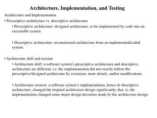
Class Categories • MFC • Dispatches system interrupts to App; Maintains Windows window • App • Dispatches user input and initiates drawing and updating cycles • Controller • Interprets user input and dispatches it to proper functions that manipulate data, ui, world, and camera • Controls i/o interactions with controlled objects (e.g. display and user input + response) • Module • Interface • Layers of data organization above raw data • Interfaces to specific pieces of raw data or worlds • World • Environment in which interfaces reside and in which user navigates through them • Provides the coordinate system and ‘physics’ of the embedded environment (e.g. for data cells it tells whether the cell contains an integer, string, percentage, etc) • Data • Lowest level/‘leaf’/raw data • View • Rendering routines and constructs • Coordinate spaces • Utilities
Dashed lines represent links (in this diagram they connect a texture map interface and canvas world interface to a data table) Dashed borders represent single instance, static, modules available to all other modules (here, these are the App and the View) Module Structure View App Screen Globe UI Stroke Globe Stroke Annotation strokes Windows Canvas World Canvases Texture Map Data Table Stroke World Texture Stroke World Data entry Data entry Data entry Stroke Stroke • Tree organization • Worlds are the non-leaf nodes • Interfaces are the edges between worlds • Data are the leaves Stroke
Controller Structure • Controllers are organized into three categories • Tools are the explicit tools available to the user through button presses • Widgets are generic constructs that invisibly control polymorphic modules when the user approaches them with generic and gestural controls • Module Controllers contain and organize the tools and widgets of each module • Controller/Module Interaction • Controller sends generic command to data module (e.g. draw, dispatch to camera controller, create window, etc) • Data module interprets and acts upon the command as it sees fit • Virtual functions implement this polymorphism
Tools • None • Dispatches to gestural widgets • Module selection, transformation, movement, and linkage are all handled by no explicit tool, as are the unitary functions within certain data modules • Pen –> StrokeWorld • CameraTool –> World->Camera • FileTool -> World, TextureMap, TextField • (Loader, Saver) • Searcher • Visualizer • (HeightMap, Timeline) • Widgets • InterfaceTransformer -> Interface • (Translator, Rotator, Scaler, FrustumRotator, FrustumPusher) • InterfaceCreator -> World • InterfaceCloser -> Interface • Linker -> World • (Group, Tag, Pipe) • Writer -> Data • (DataTableWriter, TextFieldWriter) • Module Controllers • WorldController -> World • (InterfaceCreator, Linkers, Pens, CameraTools, FileTools, Searchers, Visualizers) • InterfaceController -> Interface • (InterfaceTransformers, InterfaceCloser) • DataController -> Data • (Writers)
Coordinate Spaces • Each world defines a coordinate space • Coordinate spaces have routines to translate between each other • Embedded interfaces are organized in their parent world’s coordinate space • Interface location is coded as a cache (in absolute 3D OpenGL space) and a store (in the parent world’s coordinate space) • 3D coordinate spaces are always roots • OpenGL and camera take care of rendering objects in 3D spaces to the correct locations on the screen. • A 3D coordinate space may be inside a 2D or 3D coordinate space, but this embedding takes place using OpenGL’s viewport functionality, and can consequently only occur when the space is rendered flat on the screen. Because of this, embedded 3D worlds will be rendered as textures of the current view when working in a higher level world. When a user jumps into an embedded world, it will fill the screen and take on OpenGL’s 3D coordinate space. • 2D coordinate spaces may be embedded in each other, and they are always embedded at root in a 3D coordinate system • 2D Cartesian coordinate spaces have an origin (translation offset from parent coordinate space’s origin), a uv basis (rotation offset from 2D parent coordinate space’s uv basis, or plane in 3D parent coordinate space), and a scale (scale offset from parent coordinate space’s scale) • 2D Spherical coordinate spaces just convert from a radial parameterization to OpenGL 3D Cartesian coordinates • Origin = (0,0,0) • Scale = radius of world • Basis not used
Partial Class Hierarchy Chart Note: This is only a part of the class hierarchy. Minor classes and utility classes are not shown. CDataModule CController CInterface CWorld CViewHandler CMainFrm CTextureMap CModuleController CGlobe CCamera CWindow CMentalCanvas CTextField CWorldController CCameraGlobe CScreen CMentalCanvasDoc CCanvas CDataTable CCameraWIH CScreenController CPlaneWorld CMentalCanvasView CStroke CCameraFP CGlobeController CCanvasWorld CCommandPrompt CApp CCoordSpace CInterfaceController CStrokeWorld CLinkSet CCoordSpace2D CDataController CLink CCoordSpace2DCart CTool CTimeStamp CCoordSpace2DRad CCameraTool CFileTool CPen CSearcher CVisualizer = MFC = World CWidget = Interface = App = Controller = Data CInterfaceCreator = View CInterfaceCloser CInterfaceTransformer CWriter CLinker