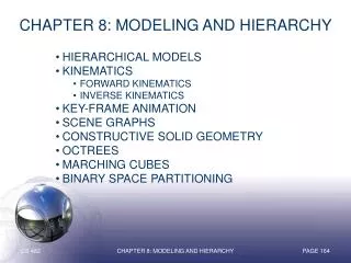
Modeling and Hierarchy
690 likes | 719 Vues
Modeling and Hierarchy. Chapter 10. Introduction: In this chapter we explore multiple approaches to developing and working with models of geometric objects. We extend the use of transformations from Chapter 4 to include hierarchical relationships among the objects.

Modeling and Hierarchy
E N D
Presentation Transcript
Modeling and Hierarchy Chapter 10
Introduction: • In this chapter we explore multiple approaches to developing and working with models of geometric objects. • We extend the use of transformations from Chapter 4 to include hierarchical relationships among the objects. • The techniques that we develop are appropriate for applications, such as robotics and figure animation, where the dynamic behavior of the objects is characterized by relationships among the parts of the model. Chapter 10 -- Modeling
The notion of hierarchy is a powerful one and is an integral part of object oriented methodologies. • We extend our hierarchical model of objects to hierarchical models of whole scenes, including cameras, lights, and material properties. • Such models allow us to extend our graphics APIs to more objet-oriented systems and gives us insight in how to use graphics over networks and distributed environments, such as the Web. Chapter 10 -- Modeling
1. Symbols and Instances • Our first concern is how to store a model that may include many sophisticated objects. • There are two immediate issues: • How do we define a complex object • How do we represent a collection of these objects. • We can take a non hierarchical approach to modeling regarding these objects as symbols, and modeling our world as a collection of symbols Chapter 10 -- Modeling
Symbols are usually represented at a convenient size and orientation. • For example: a cylinder • In OpenGL we have to set up the appropriate transformation from the frame of the symbol to the world coordinate frame to apply it to the model-view matrix before we execute the code for the symbol. Chapter 10 -- Modeling
For example: the instance transformation • M = TRS • is a concatenation of a translation, a rotation, and a scale • And the OpenGL program often contains this code: • glMatrixMode(GL_MODELVIEW); • glLaodIdentity(); • glTranslatef(...); • glRotatef(...); • glScalef(...); • glutSolidCylinder(...)’ Chapter 10 -- Modeling
We can also think of such a model in the form of a table • The table shows no relationship among the objects. However, it does contain everything we need to draw the objects. • We could do a lot of things with this data structure, but its flatness limits us. Chapter 10 -- Modeling
2. Hierarchical Models • Suppose we wish to build an automobile that we can animate • We can build it from the chassis, and 4 wheels Chapter 10 -- Modeling
Two frames of our animation could look like this: • We could calculate how far the wheel moved, and have code that looks like • calculate(speed, distance); • draw_right_front_wheel(speed, dist); • draw_left_front_wheel(speed, dist); • draw_right_rear_wheel(speed, dist); • draw_left_rear_wheel(speed, dist); • draw_chassis(speed, dist); Chapter 10 -- Modeling
BUT this is the kind of code we do NOT want.... • It is linear, and it shows none of the relationships between the 5 objects. • There are two types of relationships we wish to convey • First, we cannot separate the movement of the car from the movement of the wheels • If the car moves forward, the wheels must turn. • Second, we would like to note that all the wheels are identical and just located and oriented differently. • We typically do this with a graph. • Def: node, edge, root, leaf, ... Chapter 10 -- Modeling
Graph • Set of nodes and edges (links) • Edge connects a pair of nodes • Directed or undirected • Cycle: directed path that is a loop loop Chapter 10 -- Modeling
Tree • Graph in which each node (except the root) has exactly one parent node • May have multiple children • Leaf or terminal node: no children root node leaf node Chapter 10 -- Modeling
Tree Model of a car Chapter 10 -- Modeling
DAG Model • If we use the fact that all the wheels are identical, we get a directed acyclic graph • Not much different than dealing with a tree Chapter 10 -- Modeling
Modeling with trees • Must decide what information to place in nodes and what to put in edges • Nodes • What to draw • Pointers to children • Edges • May have information on incremental changes to transformation matrices (can also store in nodes) Chapter 10 -- Modeling
3. A Robot Arm • Robotics provides many opportunities for developing hierarchical models. • Consider this arm • It consists of 3 parts Chapter 10 -- Modeling
The mechanism has 3 degrees of freedom, each of which can be described by a joint angle between the components • In our model, each joint angle determines how to position a component with respect to the component to which it is attached Chapter 10 -- Modeling
Articulated Models • Robot arm is an example of an articulated model • Parts connected at joints • Can specify state of model by giving all joint angles Chapter 10 -- Modeling
Relationships in Robot Arm • Base rotates independently • Single angle determines position • Lower arm attached to base • Its position depends on rotation of base • Must also translate relative to base and rotate about connecting joint • Upper arm attached to lower arm • Its position depends on both base and lower arm • Must translate relative to lower arm and rotate about joint connecting to lower arm Chapter 10 -- Modeling
Required Matrices • Rotation of base: Rb • Apply M = Rb to base • Translate lower arm relative to base: Tlu • Rotate lower arm around joint: Rlu • Apply M = Rb Tlu Rlu to lower arm • Translate upper arm relative to upper arm: Tuu • Rotate upper arm around joint: Ruu • Apply M = Rb Tlu Rlu Tuu Ruu to upper arm Chapter 10 -- Modeling
OpenGL Code for Robot robot_arm() { glRotate(theta, 0.0, 1.0, 0.0); base(); glTranslate(0.0, h1, 0.0); glRotate(phi, 0.0, 1.0, 0.0); lower_arm(); glTranslate(0.0, h2, 0.0); glRotate(psi, 0.0, 1.0, 0.0); upper_arm(); } Chapter 10 -- Modeling
Tree Model of Robot • Note code shows relationships between parts of model • Can change “look” of parts easily without altering relationships • Simple example of tree model • Want a general node structure for nodes Chapter 10 -- Modeling
Code for drawing part or pointer to drawing function • Possible Node Structure linked list of pointers to children matrix relating node to parent Chapter 10 -- Modeling
Generalizations • Need to deal with multiple children • How do we represent a more general tree? • How do we traverse such a data structure? • Animation • How to use dynamically? • Can we create and delete nodes during execution? Chapter 10 -- Modeling
4. Trees and Traversals • Here we have a box-like representation of a human figure and a tree representation. Chapter 10 -- Modeling
Building the Model • Can build a simple implementation using quadrics: ellipsoids and cylinders • Access parts through functions • torso() • left_upper_arm() • Matrices describe position of node with respect to its parent • Mlla positions left lower arm with respect to left upper arm Chapter 10 -- Modeling
Tree with Matrices Chapter 10 -- Modeling
Display and Traversal • The position of the figure is determined by 11 joint angles (two for the head and one for each other part) • Display of the tree requires a graph traversal • Visit each node once • Display function at each node that describes the part associated with the node, applying the correct transformation matrix for position and orientation Chapter 10 -- Modeling
Transformation Matrices • There are 10 relevant matrices • M positions and orients entire figure through the torso which is the root node • Mh positions head with respect to torso • Mlua, Mrua, Mlul, Mrul position arms and legs with respect to torso • Mlla, Mrla, Mlll, Mrll position lower parts of limbs with respect to corresponding upper limbs Chapter 10 -- Modeling
4.1 A Stack-Based Traversal • Set model-view matrix to M and draw torso • Set model-view matrix to MMh and draw head • For left-upper arm need MMlua and so on • Rather than recomputing MMlua from scratch or using an inverse matrix, we can use the matrix stack to store M and other matrices as we traverse the tree Chapter 10 -- Modeling
Traversal Code figure() { glPushMatrix() // save present model-view matrix torso(); glRotate3f(…); // update model-view matrix for head head(); glPopMatrix(); // recover original model-view matrix glPushMatrix(); // save it again glTranslate3f(…); // update model-view matrix glRotate3f(…); // for left upper arm left_upper_arm(); glPopMatrix(); // recover and save original glPushMatrix(); // model-view matrix again ... Chapter 10 -- Modeling
Analysis • The code describes a particular tree and a particular traversal strategy • Can we develop a more general approach? • Note that the sample code does not include state changes, such as changes to colors • May also want to use glPushAttrib and glPopAttrib to protect against unexpected state changes affecting later parts of the code Chapter 10 -- Modeling
5. Use of Tree Data Structures • Need a data structure to represent tree and an algorithm to traverse the tree • We will use a left-child right sibling structure • Uses linked lists • Each node in data structure is two pointers • Left: next node • Right: linked list of children Chapter 10 -- Modeling
Left-Child Right-Sibling Tree Chapter 10 -- Modeling
Tree node Structure • At each node we need to store • Pointer to sibling • Pointer to child • Pointer to a function that draws the object represented by the node • Homogeneous coordinate matrix to multiply on the right of the current model-view matrix • Represents changes going from parent to node • In OpenGL this matrix is a 1D array storing matrix by columns Chapter 10 -- Modeling
C Definition of treenode typedef struct treenode { Glfloat m[16]; void (*f)(); struct treenode *sibling; struct treenode *child; } treenode; Chapter 10 -- Modeling
Defining the torso node treenode torso_node, head_node, lua_node, … ; /* use OpenGL functions to form matrix */ glLoadIdentity(); glRotatef(theta[0], 0.0, 1.0, 0.0); /* move model-view matrix to m */ glGetFloatv(GL_MODELVIEW_MATRIX, torso_node.m) torso_node.f = torso; /* torso() draws torso */ Torso_node.sibling = NULL; Torso_node.child = &head_node; Chapter 10 -- Modeling
Notes • The position of figure is determined by 11 joint angles stored intheta[11] • Animate by changing the angles and redisplaying • We form the required matrices usingglRotateandglTranslate • More efficient than software • Because the matrix is formed in model-view matrix, we may want to first push original model-view matrix on matrix stack Chapter 10 -- Modeling
Preorder Traversal void traverse(treenode *root) { if(root == NULL) return; glPushMatrix(); glMultMatrix(root->m); root->f(); if(root->child != NULL) traverse(root->child); glPopMatrix(); if(root->sibling != NULL) traverse(root->sibling); } Chapter 10 -- Modeling
Notes • We must save model view matrix before multiplying it by node matrix • Updated matrix applies to children of node but not to siblings which contain their own matrices • The traversal program applies to any left-child right-sibling tree • The particular tree is encoded in the definition of the individual nodes • The order of traversal matters because of possible state changes in the functions Chapter 10 -- Modeling
Dynamic Trees • If we use pointers, the structure can be dynamic typedef treenode *tree_ptr; tree_ptr torso_ptr; torso_ptr = malloc(sizeof(treenode)); • Definition of nodes and traversal are essentially the same as before but we can add and delete nodes during execution Chapter 10 -- Modeling
6. Animation • This section discusses basic animation • It then introduces kinematics and inverse kinematics. Chapter 10 -- Modeling
7. Graphical Objects • Limitations of Immediate Mode Graphics • When we define a geometric object in an application, upon execution of the code the object is passed through the pipeline • It then disappears from the graphical system • To redraw the object, either changed or the same, we must reexecute the code • Display lists provide only a partial solution to this problem Chapter 10 -- Modeling
7.1 Methods, Attributes, and Messages • OpenGL and Objects • OpenGL lacks an object orientation • Consider, for example, a green sphere • We can model the sphere with polygons or use OpenGL quadrics • Its color is determined by the OpenGL state and is not a property of the object • Defies our notion of a physical object • We can try to build better objects in code using object-oriented languages/techniques Chapter 10 -- Modeling
Imperative Programming Model • Example: rotate a cube • The rotation function must know how the cube is represented • Vertex list • Edge list cube data glRotate Application results Chapter 10 -- Modeling
Object-Oriented Programming Model • In this model, the representation is stored with the object • The application sends a message to the object • The object contains functions (methods) which allow it to transform itself Application Cube Object message Chapter 10 -- Modeling
C/C++ • Can try to use C structs to build objects • C++ provides better support • Use class construct • Can hide implementation using public, private, and protected members in a class • Can also use friend designation to allow classes to access each other Chapter 10 -- Modeling
7.2 A Cube Object • Suppose that we want to create a simple cube object that we can scale, orient, position and set its color directly through code such as cube mycube; mycube.color[0]=1.0; mycube.color[1]=mycube.color[2]=0.0; mycube.matrix[0][0]=……… Chapter 10 -- Modeling
Cube Object Functions • We would also like to have functions that act on the cube such as • mycube.translate(1.0, 0.0,0.0); • mycube.rotate(theta, 1.0, 0.0, 0.0); • setcolor(mycube, 1.0, 0.0, 0.0); • We also need a way of displaying the cube • mycube.render(); Chapter 10 -- Modeling
Building the Cube Object class cube { public: float color[3]; float matrix[4][4]; // public methods private: // implementation } Chapter 10 -- Modeling