Optical Interconnection Networks
Optical Interconnection Networks. M. S. Thesis Defense Presentation by Ch’ng Shi Baw Advisor: Prof. Mark A. Franklin. Design, Analysis, and Simulation Study of. 20 April 1999. Presentation Organization. Introduction Background information & related work Thesis Contribution


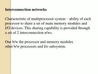
Optical Interconnection Networks
E N D
Presentation Transcript
Optical Interconnection Networks M. S. Thesis Defense Presentation by Ch’ng Shi Baw Advisor: Prof. Mark A. Franklin Design, Analysis, and Simulation Study of 20 April 1999
Presentation Organization • Introduction • Background information & related work • Thesis Contribution • Interconnection Network Simulator Framework • Improving the Gemini interconnect architecture • Conclusion • Summary and future work
Thesis Contributions • Interconnection Network Simulator (ICNS) framework • Design of the ICNS framework • Simulator Verification • Study of the Gemini network • Performance analysis • Improving Gemini’s throughput • Adding fair-scheduling capability to Gemini
Introduction • Interconnection network in generic terms • Motivation: why optics • Overview of enabling technologies • The Gemini interconnect architecture and related works • Simulation tool to aid design and study of interconnection networks
Interconnection Network • Terminals generate and/or consume data messages • e.g.: CPU, sensor banks, disks, other I/O devices • Links and switches transport data
Motivation • Want to solve large problems fast. • Target problems that are compute-, data-, and communications-intensive: • need multiple processors and high speed networks to connect processors. • want high bandwidth and low latency • Use optics to build interconnection networks
Motivation: Why Optics • Strengths of optics: • very high bandwidth (tens of Tb/s in one fiber) • low electro-magnetic interference • virtually no transmission line effects at high speed • Weaknesses of optics (current technology): • unsuitable to implement logical functions • optical components are generally costly
Optics: Technology Overview • Guided-wave optics • Free-space optics • “Smart Pixel Array” Arrays of VCSELs and detectors
Optics: Technology Overview • Free-space optics and “Smart Pixel Array” • Potential to provide physically clutter-free interconnect • Limited distance spanning capability • Insufficient reliability study
“Smart Pixel Array” ring architecture. [Chen98, Gourlay98, Lacroix98, Franklin]
Optics: Technology Overview • Guided-wave Optics • Fiber optics (mature, widely deployed) • Polymer wave guides • Recent developments: • polymer wave guides layout technology [Eldada96] • efficient fiber-to-polymer wave guide coupling [Barry97] • electro-optical switching elements [Sneh96, Lucent97]
Electro-optical Switching • The y-branch: • Refraction index of LiNbO3 changes in the presense of electric field.
Building on the y-branch • A 2x2 electro-optical switch • Issues: power loss and crosstalk. • Circuit-switched. No Buffering.
Reducing Crosstalk • Time-Dilation [Qiao96] • Reduce crosstalk using scheduling technique • Space-Dilation • Add hardware
Space-dilation technique used by Lucent Technologies [Lucent97]. Next: Gemini Network Overview
The Gemini Network • Use two networks • one optically switched (Banyan topology to reduce power loss) • one electronically switched • as proposed, the two networks have identical topology [Chamberlain97] • Main idea: • off-load bulk data to high-bandwidth optical network • maintain low-latency in lightly-loaded electrical network to cater for control messages • Goals (not related to performance): • easily manufacturable (low cost) • forward compatibility
The Gemini Network • Layout polymer wave guides using wire-printing techniques [Eldada96] • Board level connection employs polymer-to-fiber coupling technique [Barry97] • Assume space-dilation (use Lucent switch [Lucent97])
Related Work • Pan, Qiao, and Yang [Pan99] • Use 2x2 electro-optical switches • Banyan topology • Rely on time-dilation technique
Time-Dilation • Construct Contention-and-Conflict Free (CF) mappings • enforce switch element disjoint (SED) condition • schedule connections so that no two connections share a switch element • Assumes that a laser source can be completely turned off.
Example A set of CF-mappings for a 4x4 network. • Challenge is to find an optimal set of mappings for a given (arbitrary) set of connections • Need 8 mappings for a 16 connections in a 4x4 network • Need about 50 for 1000 connections (32x32 network) • Polynomial time algorithm by Qiao to construct optimal set of CF-mappings [Qiao96] • Assume the existence of a centralized controller Next: The Need of a Simulation Tool
Simulation Tool • Simulation tools are generally helpful in the study of queueing systems • Need an extensible simulator • vast interconnection network design space • want the ability to easily extend simulator to simulate future optical network components • Tune network design to specific applications • want the ability to incorporate application models into simulation Next: Thesis Contribution
Thesis Contributions • Interconnection Network Simulator (ICNS) framework • Design of the ICNS framework • Simulator and Simulation Verification • Study of the Gemini network • Performance analysis • Improving Gemini’s throughput • Adding fair-scheduling capability to Gemini
Interconnection Network Simulator(ICNS) • Process-based discrete event simulation engine. • Object-oriented design. • Implementation environment: • Uses the MODSIM III language developed by CACI Products Company. • MODSIM III C++ executable. • Simulation engine and MODSIM III to C++ compiler by CACI. • C++ to executable compiler is gcc. • Developed in Solaris 2.5 environment. First Major Contribution of Thesis
ICNS Framework: Base Classes • MessageObj • models messages • provides uniform interface to NodeObj • NodeObj • abstract base class to be subclassed to model links, switches, terminals, etc. • provides uniform interface to MessageObj • NetworkObj • container of NodeObj’s • provide identifier-to-object-reference translation service
Progression of a Simulation • Interactions between MessageObj and NodeObj drive simulation forward. • MessageObj’s operation: • Engaging a NodeObj: • Ask if NodeObj is busy • If it is, ask to be queued and terminate • Ask to be processed otherwise • Wait for the processing to finish (elapse simulation time) • Terminate
Progression of a Simulation • NodeObj’s operations: • When asked if it is busy: • answer yes or no • When asked to queue a MessageObj • action depends on queueing policy (subclass-specific) • When asked to process a MessageObj • action depends on which object is being simulated (subclass-specific) • tell MessageObj how long to wait
Description of Selected Objects • Message • Link • Terminal • Message Generator • Buffer • Central Processing Unit (CPU) • Switch
The Link Object • A Simple Link • A Multichannel Link
The Terminal Object • Processing Node Model • Processing Node Model
The Switch Object • The 2x2 Switch Model
An ICNS Application: sim • Separates topology from other network parameters • Topology descriptor file (text file) • Parameter descriptor file (text file) • ParamObj • parses parameter descriptor file • keeps track of all network parameters • BuildGNetwork Procedure • procedure parses topology descriptor file, instantiates and initializes objects accordingly
sim: User Interface • hand edit parameter file and topology file • or use Java-based GUI tools to generate files • to invoke the sim program, type sim param_file topology_file
Simulator Verification • Examine event trace (for small simulations) • Use visualization tool (for medium size simulations) • Visualization tool driven by event trace • Visualization developed by Wrighton [WUCCRC-99-02] • Simulate systems with known analytical results • Compare simulation results to analytical results Next: Visual Demonstration
M/M/1 and M/D/1 Simulations • Verification Example: • Simulate parallel M/M/1 and M/D/1 systems
M/M/1 and M/D/1 Simulations • Within 3% of analytical results for loads up to about 92%
Simulation Verification • Simulate for long enough time to get valid statistics • Wait out transient states to get valid steady-state statistics • Demonstrated that simulator produced valid results for a wide range of loads • within 3% of analytical results for loads up to 92% Next: The Gemini Network
The Gemini Network [Chamberlain97] • Architecture Overview • Network Model • Terminal Model • Switch Model • Basic Protocol • Performance Limits • Simulation Results • Improvements ...
Gemini Architecture Overview • Network Model • Banyan topology • Bufferless, optically circuit-switched network • Buffered, electronically packet-switched network
Gemini Architecture Overview • Terminal Model • CPU module models applications • One pair of optical output port • One pair of electrical output port
Gemini Architecture Overview • Switch Model • Electrical switch controls optical switch
Gemini Network Protocol • Original Protocol • Rely on Negative ACK • Fire-on-timeout mechanism • Issue: • How to set timeout parameter?
Evaluating Protocols... • Space Complexity • How much state information to keep (in switches) • Original protocol: O(1) per switch • Time Complexity • How many computational steps needed to (for a switch) process a control signal • Original protocol: O(1) • Performance measures • Throughput, latency, utilization, etc.
The setup-teardown Protocol • Similar to original protocol • But use positive ACK • Fire upon ACK • Signals • setup(S,D,blocked) • ackSetup(S,D) • block(S,D) • teardown(S,D) • Space Complexity O(1) per switch • Time Complexity O(1)
Switch Operation • Each switch keeps a list and a one bit optical switch state variable (= or x) • Processing a setup(S,D,blocked) signal: • determine output port • if setup already blocked, forward to output port. • Determine requested state (= or x) • if requested state conflict with current state and list is not empty • set blocked and forward to output port • else set state to requested state, add S to list, forward to output port • Processing a teardown(S,D) signal: • determine output port • if S in list, remove S from list • forward to output port
Switch Operation Complexity • Space Complexity O(1) • list size at most 2 • Time Complexity O(1) Next: Performance Analysis
Performance Limits numerator • Optical network utilization efficiency limited by • Define , Send teardown Send setup Receive ackSetup … delay ... Send optical message denominator