Download
1 / 89
940 likes | 1.3k Vues
Basics Of Networking. Created By Devendra Kumar. What is a Computer Network?. A network is a collection of computers, printers, routers, switches, and other devices that are able to communicate with each other over some transmission media. Types of Networks.

E N D
Basics Of Networking Created By Devendra Kumar
What is a Computer Network? A network is a collection of computers, printers, routers, switches, and other devices that are able to communicate with each other over some transmission media. Types of Networks There are two basic types of networks currently in existence: A Local Area Network (LAN) A Wide Area Network (WAN)
Common LAN Topologies Bus Architecture • In a bus topology: • a single cable connects each workstation in a linear, daisy-chained fashion. • signals are broadcasted to all stations, but stations only act on the frames addressed to them. Ring Architecture • In a ring topology: • Unidirectional links connect the transmit side of one device to the receive side of another device. • Devices transmit frames to the next device (downstream member) in the ring.
Star Topology In a star topology, each station is connected to a central hub or concentrator that functions as a multi-port repeater. Each station broadcasts to all of the devices connected to the hub. Physical LAN topologies are usually characterized as either bus or ring.
LAN Transmission Methods Unicast Transmission In unicast transmissions, a single data packet is sent from a source to a single destination on the network. • Unicast Process • The source addresses • the packet with the • destination address. • The packet is sent into • the network. • The network delivers the • packet to the destination.
Multicast Transmission In multicast transmissions, a single data packet is copied and sent to specific destinations on the network • Multicast Process • The source addresses the packet • using a multicast address. • The packet is sent into the • network. • The network copies the packet. • A copy is delivered to each • destination that is included in the • multicast address. Broadcast Tranmission In multicast transmissions, a single data packet is copied and sent to specific destinations on the network
Broadcast Process • The source addresses the packet with the broadcast address. • The packet is sent into the network. • The network copies the packet. • The packet copies are delivered to all destinations on the • network.
Repeaters Repeaters, located within the physical layer of a network, regenerate and propagate signals from one to another. They do not change any information being transmitted, and they cannot filter any information. Repeaters help to extend the distances of networks by boosting weak signals. Bridges Bridges are intelligent repeaters. They regenerate transmitted signals, but unlike repeaters, they can also determine destinations. Hubs Hubs connect all computer LAN connections into one device. They are nothing more than multiport repeaters. Hubs cannot determine destinations; they merely transmit to every line attached in a half-duplex mode. Routers Routers are a step up from bridges. They are able to route and filter information to different networks. Some routers can automatically detect problems and redirect information around the problem area. These are called "intelligent routers."
Switches Switches connect all computer LAN connections, the same as hubs do. The difference is that switches can run in full-duplex mode and are able to direct and filter information to and from specific destinations. WAN WAN Infrastructure
ATM Switches ATM Switches provide high-speed transfer between both LANs and WANs. Modem (modulator / demodulator) Modems convert digital and analog signals. At the source, modems convert digital signals to a form suitable for transmission over analog communication facilities (public telephone lines). At the destination, modems convert the signal back to a digital format. CSU/DSU (Channel Service Unit / Data Service Unit) CSUs/DSUs are similar to modems, however they send data in digital format across digital telephone loops. They are usually in a physical box, but they may come in two separate units: CSUs or DSUs.
Multiplexers A Multiplexer combines multiple signals for transmission over a single circuit. This allows for the transfer of various data simultaneously, such as video, sound, text, etc. Communication Servers X.25 / Frame Relay Switches
Unshielded Twisted Pair Unshielded twisted pair (UTP) cable is used for both LANs and telephone systems. UTP cables are composed of four color-coded pairs of copper conductors twisted around each other. An outer jacket provides protection and keeps the pairs in alignment. UTP cable connects to devices via 8 pin modular connectors called RJ-45 plugs. All LAN protocols can operate over UTP. Most modern LAN devices are equipped with RJ-45 jacks. Shielded Twisted Pair STP cable is also used for Data Networks. It originated with IBM's Token-Ring networks. Its shielding allows greater tolerances for protection from EMI interference, such as from flourescent light fixtures and electric motors.
Fiber Optic Cable Fiber Optic cables are the latest development in cabling technology. They are constructed from optical glass. There is a central glass filament, called the core, and surrounding layers of cladding, buffer coatings, strengthening materials, and an outer jacket. Information is transmitted by wavelengths of light. This is accomplished through devices that convert electrical signals into rapid pulses of either LED or Laser light. • Fiber optic cables offer several advantages, including: • high bandwidth capacity (many gigabits per second). • longer distances between devices (from 2 to over 60 kilometers). • immunity to electromagnetic interferences • Fiber optic cables are widely used in WANs for both voice and data communications. The primary barrier to their widespread use in LANs is the cost of electronics.
Ethernet • Ethernet was developed by Xerox in 1970. It was implemented through thicknet cable running at 10 Mbps.Ethernet is a connection media access method that allows all hosts on a network to share the same bandwidth of a link. • Ethernet actually just refers to the LAN implementations that includes three principal categories. • Ethernet / IEEE 802.3---operates at 10 Mbps on coaxial cable and twisted • pair cable. • 100-Mbps Ethernet---(also known as Fast Ethernet) operates at 100 Mbps • over twisted-pair cable. • 1000-Mbps Ethernet---( also known as Gigabit Ethernet) operates at 1000 • Mbps (1 Gbps) over fiber and twisted-pair cables. Basic Operation
Media Access Collision handling Ethernet is a "first come, first serve" environment. In such an environment, any station on the network can transmit whenever the network is quiet. A collision occurs when two stations listen for traffic, hear none, and then transmit data at the same time. Both transmissions are damaged, and the stations must retransmit at a later time. CSMA / CD
Ehernet Cabling • Striaght Through cable: used to connect • Host to switch or hub • Router to switch or hub • Four wires are used in straight-through cable to connect Ethernet devices. • 1 1 • 2 2 • 3 3 • 6 6 • Striaght Through cable: used to connect • switch to switch • Router direct to host • hub to hub • Host to host • Four wires are used as in straight-through cable to connect Ethernet devices. • 1 1 • 2 2 • 3 3 • 6 6
Rolled cable Start HyperTerminal to create a console connection and configure the device.Start Programs accessories communications HyperTerminalProvide the default settings for com1 port Although rolled cable is not used to connect any Ethernet connections together, we use this cable to connect a host to a router console serial communication (com) port. Eight wires are used in this cable to connect serial devices. 1 1 2 2 3 3 4 4 5 5 6 6 7 7 8 8
Network Model Overview In order for a computer to send information to another computer, and for that computer to receive and understand the information, there has to exist a set of rules or standards for this communication process. These standards ensure that varying devices and products can communicate with each other over any network. This set of standards is called a model. Network Model Advantages
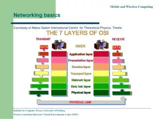
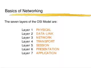
OSI Network Model There are 7 layers in the OSI model. Each layer is responsible for a particular aspect of data communication. For example, one layer may be responsible for establishing connections between devices, while another layer may be responsible for error checking during transfer. The layers of the OSI model are divided into two groups: the upper layer and lower layer. The upper layers focus on user applications and how files are represented on the computers prior to transport. For the most part, network engineers are more concerned with the lower layers. It's the lower layers that concentrate on how the communication across a network actually occurs. ALL People Seem to Need Data Processing (Layer 7 to 1) Please Do Not Take Sausage Pizzas Away (Layer 1 to 7)
The Application Layer The Application Layer is the highest layer in the protocol stack and the layer responsible for introducing data into the OSI stack. In it resides the protocols for user applications that incorporate the components of network applications. Classification of Applications Computer applications Network applications Internetwork applications Examples: Telnet, FTP, HTTP, WWW Browsers, NFS, SMTP, POP, TFTP .
Presentation Layer • The Presentation Layer manipulates the representation of data for transfer to applications on different devices. • The Presentation Layer is responsible for the following services: • Data representation • Data security • Data compression Data Representation
Session Layer The Session Layer establishes, manages, and terminates sessions (different from connections) between applications as they interact on different hosts on a network. Its main job is to coordinate the service requests and responses between different hosts for applications. Examples: NFS, SQL, RPC, ASP • Three different communication modes exists for data transfer within a session connection: • Single-duplex • Half-duplex • Full-duplex.
Transport Layer • The basic roles of the Transport Layer are to establish end-to-end connections from one computer to another on the network and provide reliable "transport" of data between devices. • Basic Transport Layer Services: • Resource Utilization (multiplexing) Connection Management (establishing) Flow Control (Buffering / Windowing) Reliable Transport (positive acknowledgment / error checking) • Flow Control Once the connection has occurred and transfer is in progress, congestion of the data flow can occur at a destination for a variety of reasons. Possible options include: • The destination can become overwhelmed if multiple devices are trying to send it data at the same time. • It may become overwhelmed if the source is sending faster than it can physically receive.
Congestion Prevention Buffering Buffering is a form of data flow control regulated by the Transport Layer. It is responsible for ensuring that sufficient buffers are available in the destination for the processing of data and that is data transmitted at a rate that does not exceed what the buffer can handle.
Windowing Windowing is a flow control scheme in which the source computer will monitor and make adjustments to the amount of information sent based on successful, reliable receipt of data segments by the destination computer. The size of the data transmission, called the "window size", is negotiated at the time of connection establishment. It is determined by the amount of memory or buffer that is available. Given a window size of 3, the source (in this case a router) sends 3 data segments to the destination. The destination sends an acknowledgement asking for the next set of data segments. If the destination does not receive all three of the negotiated data segments, for example, due to a buffer overflow, it sends no acknowledgment. Since the source does not receive an acknowledgment, it knows the data segments should be retransmitted
Network Layer • The Network Layer is the 3rd layer in the OSI model and is responsible for identifying computers on a network. This layer works closely with layer 2 to translate data packets from a logical address (similar to an IP address) into hardware based MAC addresses. • This layer is concerned with 2 functions: • Routing • Fragmentation / Reassembly • Two types of packets are used at the Network layer: • Data packets: Used to transport user data through the internetwork. Protocols used to support data traffic are called routed protocols. Eg. IP and IPX. • Route update packets: Used to update neighboring routers about the network connected to all routers within the internetwork. Protocols that send route updates are called routing protocols. Eg. RIP, EIGRP, OSPF
Data Link / Physical Layer LAN and WAN protocols occupy the bottom two layers of the OSI model. These two layers, Physical Layer and Data Link Layer, work very closely together to ensure data transfer across the physical network. Examples: HDLC, Frame Relay, PPP, ATM, FDDI, IEEE 802.3/802.2 To accomplish accurate delivery, the Data Link Layer provides the following services: 1. Machine address determination of both sending and receiving machines 2. Formatting of Network Layer "packets" into frames with machine addresses attached 3. Sequencing and resequencing of frames transmitted out of sequence Data Link Sublayers Logical Link Control (LLC) responsible for identifying Network layer protocols and encapsulating them. Media Access Control (MAC) defines how packets are placed on media
Physical Layer The Physical Layer is the lowest layer in the OSI model and is concerned with how the physical structure of the network enables transmission of data. It is responsible for defining the mechanical and electrical specifications for the transmission medium within a connection, as well as the transformation or encoding of data into “bits”. Examples:EIA/TIA-232, V.35, EIA/TIA-449, RJ-45, Ethernet, 802.3 Protocols Protocols defined at the Physical Layer standardize physical connections. Specifications include voltage levels, maximum transmission distances, data rates, and physical connectors.
Each layer depends on the service function of the ISO/OSI layer below it. To provide this service, the lower layer uses encapsulation to put the PDU from the upper layer into its data field; then it can add whatever headers and trailers the layer will use to perform its function. As networks perform services for users, the flow and packaging of the information changes. In this example of internetworking, five conversion steps occur:
TCP/IP The Transmission Control Protocol/Internet Protocol (TCP/IP) suite of protocols was developed as part of the research done by the Defense Advanced Research Projects Agency (DARPA). TCP/IP Protocol Layers • Process/Application Layer • Transport Layer or Host-to-Host Layer • Internet Layer • Network Access Layer Application protocols exist for file transfer, e-mail, and remote login. Network management is also supported at the application layer.
Transport services allow users to segment and reassemble several upper-layer applications onto the same transport-layer data stream. TCP Segment UDP Segment
IP provides connectionless, best-effort delivery routing of datagrams. It is not concerned with the content of the datagrams. Instead, it looks for a way to move the datagrams to their destination. IP Datagram Version - Version number (4 bits) Header Length - Header length in 32-bit words (4 bits) Priority and Type of Service - How the datagram should be handled. The first 3 bits are priority bits (8 bits). IP Options - Network testing, debugging, security, and others (0 or 32 bits if any)
ICMP The Internet Control Message Protocol (ICMP) is implemented by all TCP/IP hosts. ICMP messages are carried in IP datagrams and are used to send error and control messages. ICMP uses the following types of defined messages: 1. Destination Unreachable 2. Time Exceeded 3. Parameter Problem 4. Subnet Mask Request 5. Redirect 6. Echo 7. Echo Reply 8. Information Request 9. Information Reply 10.Address Request 11.Address Reply
Address Resolution Protocol Address Resolution Protocol (ARP) is used to resolve or map a known IP address to a MAC sublayer address to allow communication on a multi-access medium such as Ethernet. The term local ARP is used to describe resolving an address when both the requesting host and the destination host share the same media or wire.
Reverse ARP Reverse Address Resolution Protocol (RARP) relies on the presence of a RARP server with a table entry or other means to respond to these requests. ARP and RARP are implemented directly on top of the data link layer
IP Address In a TCP/IP environment, end stations communicate seamlessly with servers or other end stations. This communication occurs because each node using the TCP/IP protocol suite has a unique 32-bit logical IP address. Each IP datagram includes the source IP address and destination IP address that identifies the source and destination network and host. When IP was first developed, there were no classes of addresses. Now, for ease of administration, the IP addresses are broken up into classes. The bits in the first octet identify the address class. The router uses the first bits to identify how many bits it must match to interpret the network portion of the address
Class D addresses include the following: • Range of network numbers: • 224.0.0.0 to 239.255.255.255
Major Components of a Router • Random access memory (RAM) contains the software and data structures that allow the router to function. The principle software running in RAM is the Cisco IOS image and the running configuration. • Read-only memory contains microcode for basic functions to start and maintain the router. • Flash is primarily used to contain the IOS software image. Some routers run the IOS image directly from Flash and do not need to transfer it to RAM. • Non-volatile random access memory is mainly used to store the configuration. NVRAM uses a battery to maintain the data when power is removed from the router. • Configuration Register The configuration register is used to control how the router boots up.
Overview of Cisco Device Startup • This event is a series of hardware tests to verify that all components of the router are functional.POST executes from microcode resident in the system ROM. • Bootstrap code is used to perform subsequent events like finding the IOS software, loading it, and then running it. 3. The bootstrap code determines where the IOS software to be run is located. The configuration register, configuration file, or Flash memory are the normal places to house the IOS image. 4. Once the bootstrap code has found the proper image, it then loads that image into RAM and starts the IOS running 5. The default is to look in NVRAM for a valid configuration. 6. The desired configuration for the router is loaded and executed.