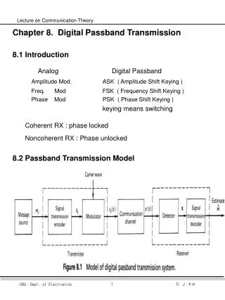
Chapter 8. Digital Passband Transmission 8.1 Introduction
921 likes | 1.57k Vues
Chapter 8. Digital Passband Transmission 8.1 Introduction Analog Digital Passband Amplitude Mod. ASK ( Amplitude Shift Keying ) Freq. Mod FSK ( Frequency Shift Keying ) Phase Mod PSK ( Phase Shift Keying ) keying means switching

Chapter 8. Digital Passband Transmission 8.1 Introduction
E N D
Presentation Transcript
Chapter 8. Digital Passband Transmission • 8.1 Introduction • Analog Digital Passband Amplitude Mod. ASK ( Amplitude Shift Keying ) • Freq. Mod FSK ( Frequency Shift Keying ) • Phase Mod PSK ( Phase Shift Keying ) • keying means switching • Coherent RX : phase locked • Noncoherent RX : Phase unlocked • 8.2 Passband Transmission Model
- Symbol (with duration T) mi alphabet {m1,m2,, mM} • (ex) Quaternary : alphabet { 00, 01, 10, 11} • - Prior probability { P(m1), P(m2), , P(mm) } • Equally likely • - Output of signal TX encoder • - Modulator : • Energy of • - ASK, FSK, PSK
- Channel : Bandpass communication channel, additive white • Gaussian noise (AWGN) channel • Channel is linear with wide bandwidth • w(t) : additive, zero-mean, stationary, white, Gaussian noise • - Average probability of symbol error • 를 minimize 하는 receiver : optimum in the minimum • probability of error sense • - Time synchronized • - Phase locked, coherent detection, coherent RX Phase unlocked, non-coherent detection, non-coherent RX
8.3 Gram-Schmidt Orthogonalization Procedure • : Representation of any set of M energy signals { si(t) } • as a linear combinations of N orthogonal basis functions • where NM. - Real-valued energy signals s1(t), s2(t),, sM(t) is in the form • where • - Real valued basic functions are orthonormal • i.e.
Gram-Schmidt orthogonalization procedure • ; Basis functions 을 구하는 방법 • Input s1(t), s2(t),, sM(t) • Let • • • Def • Then • Def • so
In general form • where • Def • - • Examples • - Fourier series expansion of a periodic signal • - Representation of a band-limited signal in terms of its • samples taken at the Nyquist rate
Example • Ex1) Gram-Schmidt Orthogonality Procedure
• • • and • • •
8.4 Geometric Interpretation of signals • In a vector form of signal • where
- :signal vector • - Signal space : N-dimensional Euclidean space • - Length or absolute value or norm : • Squared-length • - Cosine of angle between vector and • - Euclidean distance
8.5 Response of bank of correlators to noisy input • Received signal • Output of correlator j
Statistical Characterization of the Correlator Output • Let • Mean • Covariance
Define the vector of N random variables • are statistically independent • Conditional probability density fct of • 위 식을 만족하는 channel : memoryless channel • 여기서
8.6 Coherent Detection of Signals in Noise • - M possible signals : • - Received signal • - Receiver’s job : “best estimate” of TXed signal • - Represent as appropriate set of N orthonormal basis functions • represent by a point in N-dimensional Euclidean space • i.e. , transmitted signal point or message point • - Signal Constellation : Set of message points • - Decision making process : Given observation vector x, • Pe 를 최소화 하도록 x 를 mi 의estimate 으로 mapping
1. Maximum Likelihood Decoder • 1) MAP (Maximum a Posteriori) rule • Optimal decision • Select which minimize • Select which maximize • In other words, select i • : prior probability of occurrence of symbol mi • : likelihood fct that results when symbol mk • is transmitted
MAP 의 예 • 2) ML Decoder • From MAP • is independent of the transmitted signal, • Assume with equal probability • Then
In other words • Set if is maximum for k=i • Likelihood fct • So, is a monotone increasing fct. • Called the metric • ML rule • 3) Graphical interpretation of ML decision rule • Let Z denote the N-dimensional space of all possible • observation vector x • i.e. Z : observation space • Z is partitioned into M decision regions • Decision rule : • observation vector x lies in region Zi • if is maximum for k=i
Consider AWGN Channel • Metric • Decision rule : • Observation vector x lies in region Zi • if is maximum for k=i • or if is minimum for k=i • or if is minimum for k=i • Conclusion : ML decision rule is simply to choose • the message point closest to the received • signal point
a -a • 8.A Constellation (성상도) • 1. Example of constellations • The alphabet is the set of symbols that are available for transmission • - Binary antipodal (BPSK) Figure 1. Two popular constellations for passband PAM transmission. The constants b and c affect the power of the transmitted signal
4VSB 8PSK • 2. Slicer • - makes the decision about the intended symbol. • - selects that minimizes • - ML : maximum likelihood • MAP : maximum a - posteriori detector • 3. Minimum Distance • - Euclidean distance 두점 사이의 거리 • - dmin 성상도에서 가장 가까운 두점 사이의 거리 -3 -1 1 3
4. Decision Regions Figure 2 . Received samples perturbed by additive Gaussian noise form a Gaussian cloud around each of the points in the signal constellation Figure 3. The ML detectors for the constellations in Figure 1 have the decision regions shown.
5. Power constraints • ex) • Telephone channel : average power is constrained by • regulation • P(voiceband data signal) P(voice signal) • to limit crosstalk interference. • Radio channel : Power regulation • to avoid interference with other radio SVC • to avoid nonlinearity in the RF circuitry • Transmitted power • where T : symbol interval • power constraint ; • sets an upper bound on the minimum distance dmin • for any given constellation design.
6. Constellation Design • 1) objective : maximize the distance btw symbols • while not exceeding the power constraint • 2) 방법 • zero mean • 모든 점들간의 거리가 똑같이 • 모든 점들이 동일 원 내에 분포 • 3) QAM Figure 4. Some QAM constellations. Figure 5. Cross constellations.
4) AM-PM(복잡) • 5) Hexagonal constellations (복잡) • 6) Higher Dimensions ; 3rd, 4th-order Figure 6. Constellations using phase-shift keying and amplitude modulation.
8.7 Probability of Error • - Observation space Z is partitioned, in accordance with ML • decision rule, into a set of M regions • - Suppose symbol mi(signal vector Si) is TXed. • - Observation vector : x • Average probability of symbol error Pe • < Problem > Numerical computation of integral is impractical
1. Union Bound on the Probability of Error • Example of QPSK • In General
where • Thus • Avg. Probability of symbol error • For symmetric geometry • Consider • Thus
If TXed signal power >> noise spectral density No • Approximation of the bound • Mmin : # of TXed signals that attain the minimum Euclidean distance • for each mi
2. Bit Versus Symbol Error Probabilities • BER ( Bit Error Rate ) or Probability of bit error • m bits 1 symbol • 1) Case 1 • Gray code : 옆 심볼과는 1 bit만 차이 나게 design • 옆 심볼과 error 가 날 경우 1 bit error 만 나게 함 • In general
2) Case 2 • Let M=2K, where K is an integer • Assume that all symbol errors are equally likely and occur with probability • where Pe is avg. probability of symbol error • Error 가 있는 symbol 에서 번째 i bit가 error 일 확률 (2K-1경우의 수)
8.8 Correlation Receiver • - ML Decision rule • Observation vector x lies in region Zi • if is minimum for k=i • - Consider • - Other form of ML Decoder • Observation vector x lies in region Zi • if is maximum for k = i • where ; energy
8.9 Detection of signals with unknown phase • noise • Uncertaninty • phase • Synchronization with the phase of the carrier : costly • Noncoherent receiver : phase information 무시 • (조건) Information이 phase 에 실려 있지 않을 경우만 가능 • ex) FSK, non-negative ASK O.K. • PSK 적용 안됨 • Consider FSK • where • Received signal (AWGN channel) • where
Correlator output of • Correlator output of • So, Figure 8.12 Noncoherent receivers. (a) Quadrature receiver using correlators. (b) Quadrature receiver using matched filters. (c) Noncoherent matched filter.
Noncoherent matched filter • = matched filter + envelope detector
8.10 Hierarchy of Digital Modulation Techniques • Coherent • Binary, M-ary • ASK, PSK, FSK • Ex) QPSK, MSK, QAM( Hybrid ) • Non-coherent • ASK, FSK • DPSK : noncoherent form of binary PSK • 8.11 Coherent binary PSK
Only one basis fct • Signals • Euclidean distance • Avg. probability of symbol error = BER • Implementation :
0 1 0 1 • 8.12 Coherent Binary FSK • FSK • CPFSK • (Sunde’s FSK) • For Binary CPFSK • Orthonomal basis function
Euclidean distance (BPSK 와 3 dB 차이) • Avg. prob. of symbol error = BER • Implementation
8.13 Coherent QPSK • Orthonormal basis fct
Symbol error • BER with gray coding • (Observation) BPSK 와 BER 동일 • 그러나 사용 • 따라서 Coherent detection 경우 BPSK 보다 QPSK 가 좋다.
8.14 Coherent MSK • 1. Consider CPFSK • In the form of an angle-modulated signal
Symbol 1 Symbol 0 • 2. Phase Trellis • at t = Tb • Sunde’s FSK, h=1 change • MSK, change for Tb
3. Signal-space diagram • For k는 integer
4가지 경우 • Orthonormal basis fct