Download
1 / 1
10 likes | 219 Vues
Config- uration. Failure Mode. V 1. I 1. V 1 increases by. Unaffected for all switches outside failed row. Short Circuit. for. switches in different rows. Isolated String. I switch increases by. Open Circuit. V 1 unaffected for all switches. for. switches in same row.

E N D
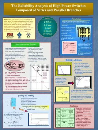
Config- uration Failure Mode V1 I1 V1 increases by Unaffected for all switches outside failed row Short Circuit for switches in different rows Isolated String Iswitch increases by Open Circuit V1 unaffected for all switches for switches in same row Vswitch increases by for Unaffected for all switches Short Circuit switches in same column Cross bridge Iswitch increases by Vswitch unaffected for all switches for Open Circuit switches in different columns The Reliability Analysis of High Power Switches Composed of Series and Parallel Branches Authors Introduction Abstract: This paper contains an analytical method for the failure analysis of a matrix configuration of switches in series and parallel. The concept is to use lower voltage and current rating switches in series and parallel to attain the higher ratings needed in power engineering applications. The analysis is based on probability state transition. A discussion of voltage and current snubbing is given. Representative results are illustrated and applications are suggested. Through the use of series and parallel connections, it is possible to utilize lower voltage and current rated switches to build up a high rating switch (e.g., for power engineering applications). G. T. Heydt D. S. James • For the case of the application of switches with voltage and current rating V and I • Nse = switches connected in a series string • Npl = parallel strings • N= Nse*Npl switches will have an equivalent rating of Nse*V, Npl*I E. S. Gel M. M. Albu N. F. Hubele PSERC • The probability of failure of a switch with applied voltage V and applied current I is qVI. • It is assumed the failure of a series switch is in the ‘shorted’ mode. • The failure of a series string is the dual phenomenon in the ‘open’ mode. The state transitiondiagram • Multiple switch failure at any • one time is possible and is • modeled • Markov chain model is used • Assume the branch • probabilities are a function • only of branch terminal states. • The probability of failure of switch • is not a function of the switch status • (i.e., ON or OFF) The probability associated with branches is indicated for selected elements for a two by two switch matrix illustration. The several branches depicted represent the conditional probability of transitioning to another state given the present system state. Reliability calculations Probability distribution of the lifetime of a matrix of series/parallel switches • What is the distribution of • lifetime for system that starts • with all switches functional? • What is the expected lifetime for • the system? • For each switching epoch, what is • the probability that the system is • nonfunctional? • Pn = the probability vector at time n • Po = [1 0 0 0 … 0] • A = state transition matrix • The general form of A is seen here where: • The matrix positions correspond to the tiers • The first tier can transition to all other tiers. In general, tier i contains all zero entries except to the right of the principal diagonal, and the diagonal itself. • The block submatrices along the principal • diagonal are diagonal matrices. • The row sum of all rows of A is unity Probability of switch failure versus number of operations for an illustrative 480 V, 100 mA switch matrix An illustration of the calculation capability of the Markov chain approach: The number of expected switch operations to attain probability 0.5 of the failure of the switch matrix versus the probability of individual switch failure. Grading and snubbing • Snubbers are often designed for • Peak voltage limiters • Rate of rise voltage limiters • Peak current limiters • Rate of rise current limiters Conclusions The function of the turn-off snubber is to limit the peak voltage across the switch during the opening period. • It is possible to assemble low • rating switches in series and • parallel for higher rating • applications. • Voltage and current snubbing • is necessary. • The failure analysis is possible • using a Markov chain. • The influence of individual • switch failure is illustrated. • A distinctive structure of the • state transition matrix, A, • for this application is • demonstrated. Assuming identical and ideal components, the voltages and currents are equal for every switch and parallel string. Vswitch (no snubber) Vswitch (with snubber) = the total power absorbed by snubber system