Download

1 / 33
380 likes | 576 Vues
41. SERIES, PARALLEL, AND SERIES-PARALLEL CIRCUITS.

E N D
41 SERIES, PARALLEL, AND SERIES-PARALLEL CIRCUITS
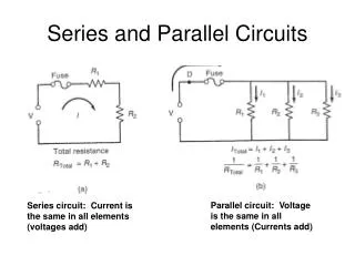
Figure 41-1 A series circuit with three bulbs. All current flows through all resistances (bulbs). The total resistance of the circuit is the sum of the total resistance of the bulbs, and the bulbs will light dimly because of the increased resistance and the reduction of current flow (amperes) through the circuit.
TECH TIP: Farsighted Quality of Electricity Electricity almost seems to act as if it “knows” what resistances are ahead on the long trip through a circuit. If the trip through the circuit has many high-resistance components, very few electrons (amperes) will choose to attempt to make the trip. If a circuit has little or no resistance (for example, a short circuit), then as many electrons (amperes) as possible attempt to flow through the complete circuit. If the flow exceeds the capacity of the fuse or the circuit breaker, then the circuit is opened and all current flow stops.
Figure 41-3 As current flows through a circuit, the voltage drops in proportion to the amount of resistance in the circuit. Most, if not all, of the resistance should occur across the load such as the bulb in this circuit. All of the other components and wiring should produce little, if any, voltage drop. If a wire or connection did cause a voltage drop, less voltage would be available to light the bulb and the bulb would be dimmer than normal.
Figure 41-4 In a series circuit the voltage is dropped or lowered by each resistance in the circuit. The higher the resistance, the greater the drop in voltage.
Figure 41-5 A voltmeter reads the differences of voltage between the test leads. The voltage read across a resistance is the voltage drop that occurs when current flows through a resistance. A voltage drop is also called an “IR” drop because it is calculated by multiplying the current (I) through the resistance (electrical load) by the value of the resistance (R).
Figure 41-6 In this series circuit with a 2-ohm resistor and a 4-ohm resistor, current (2 amperes) is the same throughout even though the voltage drops across each resistor.
FREQUENTLY ASKED QUESTION: Why Check the Voltage Drop Instead of Measuring the Resistance? Imagine a wire with all strands cut except for one. An ohmmeter can be used to check the resistance of this wire and the resistance would be low, indicating that the wire was okay. But this one small strand cannot properly carry the current (amperes) in the circuit. A voltage drop test is therefore a better test to determine the resistance in components for two reasons: • An ohmmeter can only test a wire or component that has been disconnected from the circuit and is not carrying current. The resistance can, and does, change when current flows. • A voltage drop test is a dynamic test because as the current flows through a component, the conductor increases in temperature, which in turn increases resistance. This means that a voltage drop test is testing the circuit during normal operation and is therefore the most accurate way of determining circuit conditions. A voltage drop test is also easier to perform because the resistance does not have to be known, only that the unwanted loss of voltage in a circuit should be less than 3% or less than about 0.14 volts for any 12-volt circuit.
Figure 41-11 The amount of current flowing into junction point A equals the total amount of current flowing out of the junction.
Figure 41-12 The current in a parallel circuit splits (divides) according to the resistance in each branch.
TECH TIP: The Path of Least Resistance There is an old saying that electricity will always take the path of least resistance. This is true, especially if there is a fault such as in the secondary (high-voltage) section of the ignition system. If there is a path to ground that is lower than the path to the spark plug, the high-voltage spark will take the path of least resistance. In a parallel circuit where there is more than one path for the current to flow, most of the current will flow through the branch with the lower resistance. This does not mean that all of the current will flow through the lowest resistance, because the other path does provide a path to ground, and the amount of current flow through the other branches is determined by the resistance and the applied voltage according to Ohm’s law. Therefore, the only place where electricity takes the path of least resistance is in a series circuit where there are not other paths for the current to flow.
Figure 41-13 In a typical parallel circuit, each resistance has power and ground and each leg operates independently of the other legs of the circuit.
Figure 41-14 A schematic showing two resistors in parallel connected to a 12-volt battery.
Figure 41-15 A parallel circuit with three resistors connected to a 12-volt battery.
Figure 41-16 Using an electronic calculator to determine the total resistance of a parallel circuit.
Figure 41-17 Another example of how to use an electronic calculator to determine the total resistance of a parallel circuit. The answer is 13.45 ohms. Notice that the effective resistance of this circuit is less than the resistance of the lowest branch (20 ohms).
Figure 41-18 A parallel circuit containing four 12-ohm resistors. When a circuit has more than one resistor of equal value, the total resistance can be determined by simply dividing the value of the resistance (12 ohms in this example) by the number of equalvalue resistors (4 in this example) to get 3 ohms.
Figure 41-24 This complete headlight circuit with all bulbs and switches is a series-parallel circuit.