Series and Parallel Circuits
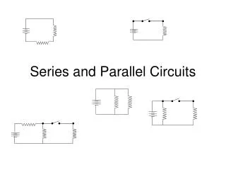
Series and Parallel Circuits. Lesson 6. The two simplest ways to connect conductors and load are series and parallel circuits. Series circu it - A circuit in which loads are connected one after another in a single path.

Series and Parallel Circuits
E N D
Presentation Transcript
Series and Parallel Circuits Lesson 6
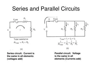
The two simplest ways to connect conductors and load are series and parallel circuits. • Series circuit - A circuit in which loads are connected one after another in a single path. • Parallel circuit – A circuit in which loads are connected side by side.
Gustav Robert Kirchhoff • Each arrangement affects the way in which potential difference and current act in the various parts of the circuit. Gustav Robert Kirchhoff studied the way each of the circuit parameters behaved in series and parallel circuits. His research led to two laws.
Kirchhoff’s current law • the total amount of current into a junction point of a circuit equals the total current that flows out of that same junction.
In the diagram to blow, three branches are coming together at one junction point and two branches leave. I1 + I2 + I3 = I4 + I5
Kirchhoff’s Voltage Law • The total of all electric potential difference in any complete circuit loop is equal to any potential increases in the circuit loop.
V1 V2 V3 VT • The potential increase, VT is equivalent to the sum of all the potential losses so that • VT = V1 + V2 + V3
Kirchhoff’s laws are particular applications of the laws of conservation of electric charge and the conservation of energy. • In any circuit, there is no net gain or loss of electric charge or energy.
30 V V2 30 V 100v 10.0 A 10.0 A 10.0 A R1 R2 I3 Example1: Kirchhoff’s law in a series circuit • A simple series circuit is seen below. Use Kirchhoff’s current and voltage laws to find the values of the missing voltage (V2) and current (I2)
Voltage • according to Kirchhoff’s law, this series circuit has one voltage increase of 100V. This voltage must be distributed so that the sum of all voltage drops for each individual resistor must equal this value.
30 V V2 30 V 100v 10.0 A 10.0 A 10.0 A R1 R2 I3 • VT = V1 + V2 + V3 • So V2 = VT – V1 – V3 • V2 = 100 V – 30 V – 30 V • = 40 V
Current • According to Kirchhoff’s current law, this series circuit has no real junction point, so it has only one path to follow. Therefore,
30 V V2 30 V 100v 10.0 A 10.0 A 10.0 A R1 R2 I3 • IT = I1 = I2 = I3 = • IT = 10 A
9.0 A R3 30V V2 R2 30V 30V R1 I3 3.0 A 3.0 A Example 2: Kirchhoff’s laws in a parallel circuit • A simple parallel circuit shown below shows how Kirchhoff’s current and voltage laws can be used to find the missing voltage (V2) and current (I3).
9.0 A R3 30V V2 R2 30V 30V R1 I3 3.0 A 3.0 A Voltage • The voltage increase is 30 V, thus there must be a decrease for each of the three different parallel resistor paths. Therefore, VT = V1 = V2 = V3 • The voltage drop across all three parallel resistors is 30 V, no matter what their resistances.
9.0 A R3 30V V2 R2 30V 30V R1 I3 3.0 A 3.0 A Current • There are 4 junction points in this diagram. One at the top and bottom of each branch, to resistors 1 and 2. The sum of the current entering the junctions must equal the sum exiting.
IT = I1 + I2 + I3 = 9 A • I3 = IT – I1 – I2 = 9 A – 3 A – 3A • = 3A
30 V V2 30 V 100v 10.0 A 10.0 A 10.0 A R1 R2 R3 Resistance in series • In a series circuit, all current must first pass through resistor 1, then 2, and so on. The voltage drops across each resistor. The sum of the voltage drops gives the overall voltage drop in the circuit.
From Kirchhoff’s law, VT = V1 + V2 + V3 • From Ohm’s law, ITRT = I1R1 + I2R2 + I3R3 • But from Kirchhoff’s law, IT = I1 = I2 = I3 • The currents factor out; IRT = IR1 + IR2 + IR3 • Therefore, RT = R1 + R2 + R3 • If all the resistors are the same, use the formula
30 V V2 30 V 100v 10.0 A 10.0 A 10.0 A R1 R2 R3 Example 3: Resistors in series • What is the series equivalent resistance of 10 Ω, 20 Ω, and 30 Ω resistors connected in series? • RT = R1 + R2 + R3 • Therefore, RT = 10 Ω + 20 Ω + 30 Ω • = 60 Ω.
Resistance in parallel • In a parallel circuit, the total current must split and distribute its self among all of the available circuit paths. • From Kirchhoff’s law, IT = I1 + I2 + I3 • From Ohm’s law • But from Kirchhoff’s law VT = V1 = V2 = V3 • The voltages factor out • Therefore,
9.0 A R3 30V V2 R2 30V 30V R1 I3 3.0 A 3.0 A • If all the resistors are the same, use the formula
Example: Resistors in parallel • What is the parallel equivalent resistance for a 25 Ω, 40 Ω, and 10 Ω resistors wired in parallel?
This can calculated easily on the calculator by using the fraction button. • a b/c button • = 33/200 • RT = 200 / 33 = 6.1
Questions • Calculate the total resistance for the following: • Three resistors, each 20 Ω, connected in series • Three resistors, each 20 Ω, connected in parallel • Calculate the total current in a parallel circuit with current of I1 = 2.1 A in resistor 1, I2 = 3.1 in resistor 2 and I3 = 4.2 in resistor 3. • Calculate the total potential difference in a series circuit with a potential difference of V1 = 12 V in resistor 1, V2 = 14 V in resistor 2 and V3 = 16 V in resistor 3. • Calculate the equivalent resistance of a circuit with the flowing resistors in parallel: 5 Ω, 10 Ω, and 30 Ω. • A 1.0 Ω resistor is hooked up to a 1.0 x 10⁶ Ω resistor in a) series , b) parallel. For each situation, calculate the total resistance and explain the dominance of one resistor in the total value.