HW-SW Co-Simulation
HW-SW Co-Simulation. 王甦群 R91921007 Graduate Institute of Electrical Engineering National Taiwan University July 3, 2003. Outline. Basic concepts of simulation. Case study. Conclusions. What is Verification?.

HW-SW Co-Simulation
E N D
Presentation Transcript
HW-SW Co-Simulation 王甦群 R91921007 Graduate Institute of Electrical Engineering National Taiwan University July 3, 2003
Outline • Basic concepts of simulation. • Case study. • Conclusions.
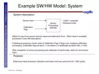
What is Verification? • Verification is the task of ensuring that a design is correct and complete. Such assurance can prevent time-consuming debugging at low abstraction levels and iterating back to high abstraction levels. • Correctness means that the design implements its specification accurately. • Completeness means that the design’s specification described appropriate output responses to all relevant input sequences. A ? + C B If C=A+B
Methods of Verification • Formal verification is an approach of verification that analyzes a design by prove or disprove certain properties. • Simulation is an approach in which we create a model of the design that can be executed on a computer. We provide sample input values to this model, and check that the output values generated by the model match our expectation. Verification Formal Verification Simulation
Simulation V.S. Physical Implementation • Compare with a physical implementation, simulation has several advantages. The two most important advantages are excellent controllability and observablility. • Controllability is the ability to control the execution of the system. • Observability is the ability to examine system value. • With excellent controllability and observability, simulation allows a designer to perform debugging that would have been nearly impossible on a physical implementation. Input Output
Simulation V.S. Physical Implementation • Simulation also has several disadvantages compared with a physical implementation: • Setting up simulation could take much time for systems with complex external environments. A designer may spend more time modeling the external environments than the system itself. • The models of the environments will likely to be somewhat incomplete, so may not model complex environment behavior correctly, especially when the behavior is undocumented. • Simulating speed can be quite slow compared to execution of a physical implementation.
Simulation Speed 1 hour IC 1 1 day x10 FPGA 4 days Emulation x100 1.4 months x1000 Throughput Model x10,000 1.2 years ISS Simulation x100,000 Cycle-accurate Simulation 12 years x1,000,000 RTL HDL Simulation > 1 lifetime x10,000,000 Gate-level Simulation 1 millennium
Simulation Speed • Why so slow? • We are sequentializing a parallel hardware design. • We are adding several programs in between the system being simulated and real hardware. • How to gain speed? • Use emulator. • Use simulation model with higher level.
Emulator • Advantage of Emulator • The environment setup needed with simulation is not necessary. • Disadvantage of Emulator • Still not as fast as real implementations, which could lead to timing problems in the real environment. • Costly.
How the Industry Looks at the Many Language Choices www.cadence.com A Single Language Alone Cannot Effectively Cover All of the Design Flow !!
Hardware-Software Co-Simulation [4] System Specification Functional SW model Functional HW model SW HW Virtual Prototype System Instruction-true Synthesis Model VHDL Processor Simulator Cosimulation Environment Cycle-true Gate Model Processor Simulator Physical prototype
Case Study [2] • System Partitioning • Multi-thread Program Generation • Interface Generation HardwareC description System Graph Model C Program ASIC Graph Model VULCAN-II System Input Interface Graph Model POSEIDON (Simulator) Assembly Code ASIC and interface Netlist Mixed System Implementation System Output
Target System Architecture MEMORY ML Program Interface Buffer User’s Data ASIC MICRO- PROCESSOR ASIC
System Synthesis Example Controller Graph Model Partitioning and Program threads generation Behavioral Synthesis Process cg(q,x,y…){ …. } HardwareC Code Hardware Component Software Component Graphics Controller line( ) Hardware Graph Model circle( ) Interface Circuitry
Event-Driven Simulation of a Mixed System Design System Graph Model Ariadne SLIF Netlist (Gate-level Description) DLX Assembly Code DLX Simulator Mercury POSEIDON • Implements: • Interface protocol between models • Event-driven simulation of multiple models • Multiple clocks and clock rates between models
Simulation Example of Producer-Consumer Pair Producer #Models model IO io 1.0 /local/ioDir IO; model p dlx 1.0 /local/ProducerDir Producer; model C mercury 3.0 /local/ConsumerDir Consumer; #Connections queue [4] comm [3]; C.RESET=IO.RESET; C.r[0:0]=IO.r[0:0]; #communication protocol P.0xff004[0:0] = ! comm.full; C.b_rq=!comm.empty; when (P.0xff000_wr+ & !comm.full) do comm[0:3] enqueue P.0xff000[0:3]; when (C.b_ak+ & !comm.empty) do comm[0:3] dequeue C.b[0:3]; #Outputs IO.inChannel[0:3]=P.0xff000[0:3]; IO.outPort[0:3]=C.c[0:3] IO.InRq=P.0xff000_wr; IO.OutAk=C.b_ak; SW InRq comm OutAk Consumer HW OutPort
Example of Graphics Controller Line Line data queue PROCESSOR Coordinate Circle Circle data queue FIFO Control Schedule Control FIFO ASIC Hardware int lastPC[MAXCRS]=(scheduler,circle,line,main); int current=MAIN; int *controlFIFO=(int*)0xaa0000; int *controlFIFO_rq=(int*)0xaa0004; main(){resume(SCHEDULER)}; int nextCoroutine; scheduler(){resume(LINE); resume(CIRCLE); while(!RESET){do{nextCoroutine=*controlFIFO} while((nextCoroutine&0x4))!0x4); resume(nextCoroutine&0x3); } Software Component: main program
Example of Graphics Controller Specification of the graphics controller model qc io 1.0 DIR GraphicsController; model ccoord mercury 5.0 DIR gcircle; model lcoord mercury 5.0 DIR gline; model mp dlx 1.0 DIR main; model CF mercury 1.0 DIR control; queue [1] lqueue [16], cqueue [16]; queue [3] controlFifo [2]; CF.r[0:0]=lcoord.run[0:0]=ccoord.run[0:0]=gc.run[0:0]; CF.RESET=lcoord.RESET=ccoord.RESET=gc.RESET; CF.lqr[0:0]=!lqeue.empty; CF.lak[0:0]=mp.0xee004_rd; CF.crq[0:0]=!cqueue.empty; mp.0xee004[0:0]=!cqueue.empty; mp.0xee004[0:0]=!lqueue.empty; continued~
Example of Graphics Controller ~continued #Lqueue when (lcoord.run_rq+ & !lqueue.full) do lqueue[15:0] enqueue lcoord.queue[15:0]; lcoord.queue_ak=!lqueue.full; when (mp.0xff000_rd+ & !lqueue.empty) do lqueue [15:0] dequeue mp.queue[15:0]; mp.queue_ak=!lqueue.empty; ….. #ControlFifo when (CF.outline_rq+ & !conrtolFifo.full) do controlFifo[1:0] enqueue outline[1:0]; CF.outline_ak=!controlFifo.full; ….. #Output specification gc.x_out[7:0]=mp.0xff100[7:0]; gc.y_out[7:0]=mp.0xff104[7:0]; gc.controlFifo[1:0] =controlFifo[1:0]; gc.CF_ready=!controlFifo.empty;
Example of Graphics Controller POSEIDON Output Specification
Conclusions • Due to the heterogeneity of these components and the drastically increased number of gates per chip, verification of the complete system and simulation speed has become the critical bottleneck in the design process. • To increase the productivity and shorten time to market it is important to be able to verify a heterogeneous SOC design at an early stage of the development process to prevent expensive re-design.
Reference [1] F. Vahid, and T. Givargis, Embedded System Design: A Unified Hardware/Sofware Introduction, 2002, John Wiley & Sons Inc. [2] Rajesh k. Gupta, Claudionor Nunes Coelho, Jr. and Giovanni De Micheli,”Synthesis and Simulation of Digital Systems Containing Interfacting Hardware and Software Components” IEEE Design Automation Conference, 1992. [3] David Becker, Raj K. Singh, Stephen G. “An Engineering Environment for Hardware/Software Co-Simulation” IEEE Design Automation Conference, 1992. [4] Andreas Hoffmann, Tim Kogel and Heinrich Meyr “A Framework for Fast Hardware-Software Co-simulation” IEEE Design, Automation and Test in Europe, 2001 Conference and Exhibition 2001.